


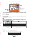
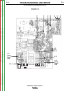

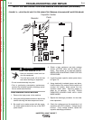
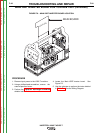
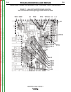
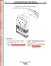

INPUT FILTER BOARD
-
Checks
the
correct
voltages
as
indicated
on
the
above
drawing
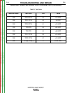
CN 1/1-2 CN 1/3-4
VAC 2.3V (1.2V)
“PE”
EARTH CONNECTION
POWER SUPPLY “OUT” 230V (115V)
230V (115V)
POWER SUPPLY “IN” 230V (115V)
RV1 RV2
PZ1 PZ2
FIGURE F.5 – INPUT FILTER BOARD
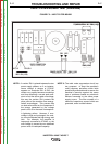
INPUT FILTER BOARD TEST (continued)
NOTE 1: A varistor ZN1 is placed between the two
power supply phases, so if an instanta-
neous voltage in excess of 275VAC
appears on terminals RV1 & RV2, the
varistor very rapidly becomes conductive
and thus absorbing a current peak suffi-
cient to limit the above said overvoltage;
this way the varistor ZN1 protects the
other parts of the machine from energy-
limited overvoltages. This process has
no destructive effect on the component if
the energy generated by the voltage
peak is low, as in the case of atmospher-
ic lightening strikes. However, if over-
voltage is high and prolonged, the varis-
tor cannot dissipate this high energy and
fails. For example, the machine is
improperly connected to 275VAC, or the
over-voltage is caused by non stabilized
power units of inadequate capacity.
NOTE 2: The radio noise suppression circuit has
two purposes: to keep the machine’s
radio frequency emissions within limits
specified by standards and to ensure the
machine’s immunity against the same
type of problems caused any electronic
devices connected to the same power
supply source. The filter consists of a
network of capacitors, some of which are
grounded, and a toroidal inductor.
TROUBLESHOOTING AND REPAIR
F-17 F-17
INVERTEC® V205-T AC/DC™
Return to Section TOC Return to Section TOC Return to Section TOC Return to Section TOC
Return to Master TOC Return to Master TOC Return to Master TOC Return to Master TOC