


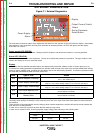

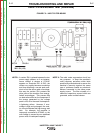
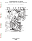

INPUT FILTER BOARD
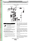
FIGURE F.4 – INPUT FILTER BOARD LOCATION
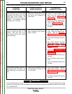
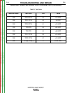
INPUT FILTER BOARD TEST (continued)
PROCEDURE
1. Remove input power to the V205-T.
2. Using a phillips head screwdriver, remove the
case wraparound.
3. Perform the Input Filter Capacitor Discharge
Procedure detailed earlier in this section.
4. Locate the Input Filter board. See Figure F.4.
5. See Note 1 and Note 2..
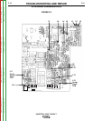
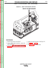
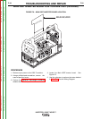
6. See Figure F.5 for voltage checks.
TROUBLESHOOTING AND REPAIR
F-16 F-16
INVERTEC® V205-T AC/DC™
Return to Section TOC Return to Section TOC Return to Section TOC Return to Section TOC
Return to Master TOC Return to Master TOC Return to Master TOC Return to Master TOC