


THEORY OF OPERATION
E-4 E-4
INVERTEC® V205-T AC/DC™
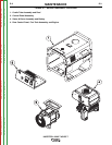
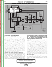
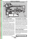
MAIN TRANSFORMER
The 100KHZ output of the Main IGBT Inverter Board is
coupled, through a DC Blocking Capacitor Board, to
the primary of the Main Transformer. The transformer
reduces the high voltage (low current) input applied to
the primary winding and through transformer action
develops a lower secondary voltage capable of high
output currents.
OUTPUT MODULE AND CLAMPING
BOARD
The AC output of the Main Transformer is applied to
the Output Modules for full wave rectification. The
Clamping Diodes function as a filter eliminating any
pulsed over-voltages that may be present at the Output
Modules. The Clamping Board protects the Output
Modules from damage due to higher than normal volt-
age spikes.
FIGURE E.4 - MAIN TRANSFORMER, OUTPUT DIODE MODULE & CLAMPING BOARD,
OUTPUT TRANSISTOR MODULE & SUPERIMPOSITION BOARD
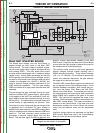
OUTPUT MODULE TRANSISTOR
BOARD
This module produces the AC waveforms and frequen-
cies. It receives command signals from the
Superimposition Board. Depending on which of the
two IGBTs is active at any given moment the welding
output of the machine can be either positive or nega-
tive AC or DC.
SUPERIMPOSITION BOARD
The Super Imposition Board receives signals from the
Control/Display Board to control the status of the sec-
ondary inverter portion of the V205T machine. This
board also generates voltage pulses at about +/-
200VDC that facilitate the re-striking of the arc when
the TIG AC welding current is being utilized. The
Superimposition Board internally generates the auxil-
iary power supply for the isolated piloting of the power
elements (IGBTs) for the Output Module Transistor
Board. The Superimposition Board plugs directly into
the Bus Board.
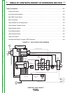
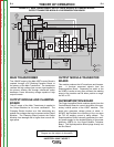
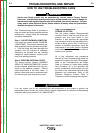
NOTE: Unshaded areas of Block Logic
Diagram are the subject of discussion
Superimposition
board
Bus board
Fan
Input
board
HF
board
Main IGBT
& Power board
4
IGBT's
Control board
Display & LED
board
888
Control
Knob
Gas
Solenoid
DC blocking
capacitor board
Main
Transformer
Output
board
Output
Transistor
Module
Current
Hall
Device
Output
Filter bd.
(bypass)
(D + E)
Remote 2/4
Remote
75, 76, 77
A, B, C
24 VDC Remote 2/4 path (D + E)
turn on AC ckt.
+15, -15, +5
input volt meter
thermostat info
set info
input current meter
turn on PWM
HF control signal
+48, +24
Input
Choke
_
+
RF coil
-48, +24,+15,-15,+5
reconnect info.
voltage feedback
high volt supply
turn on AC ckt.
current feedback
IGBT
Thermostats
Output
Diode
Thermostat
Voltage Feedback
Current Feedback
AC DC Gate drive signals
24 VDC
48 VDC
Output
Choke
Return to Section TOC Return to Section TOC Return to Section TOC Return to Section TOC
Return to Master TOC Return to Master TOC Return to Master TOC Return to Master TOC