


THEORY OF OPERATION
E-5 E-5
INVERTEC® V205-T AC/DC™
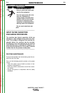
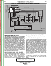
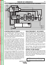
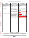
CONTROL/DISPLAY BOARD
The Control/Display Board assembly is actually two
boards mounted together. They should be replaced
together. The Display portion houses the control
panel, LEDs, push buttons and output encoders. The
Display Boards functions as the interface between the
user and the V205-T machine.
The Control Board functions as the support circuitry for
the on board CPU (micro-processor). The Control
Board receives information and power from the Bus
Board, and Main IGBT Inverter Board. The Control
Board supplies power for the Display Board and sup-
plies signals for the Display Board to show set and
actual current values, error codes and pre-set values.
It also accepts signals via the Output Filter Board (Pins
D and E- 24VDC) to initiate welding output. Upon clo-
sure of D and E a 24VDC relay is activated to indicate
that welding output is required. The Control Board
CPU sends a command to the Main IGBT Inverter
Board to activate the welding IGBTs. The remote con-
trol signals (Pins A, B&C) are also fed into the
Control/Display Board from the 6 pin connector located
on the front of the machine. Based upon current and
voltage feedback information the Control Board regu-
lates the welding output to coincide with the pre-set
welding commands. The Control/Display Board also
activates and controls the High Frequency Board, the
gas solenoid and the Super Imposition Board.
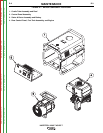
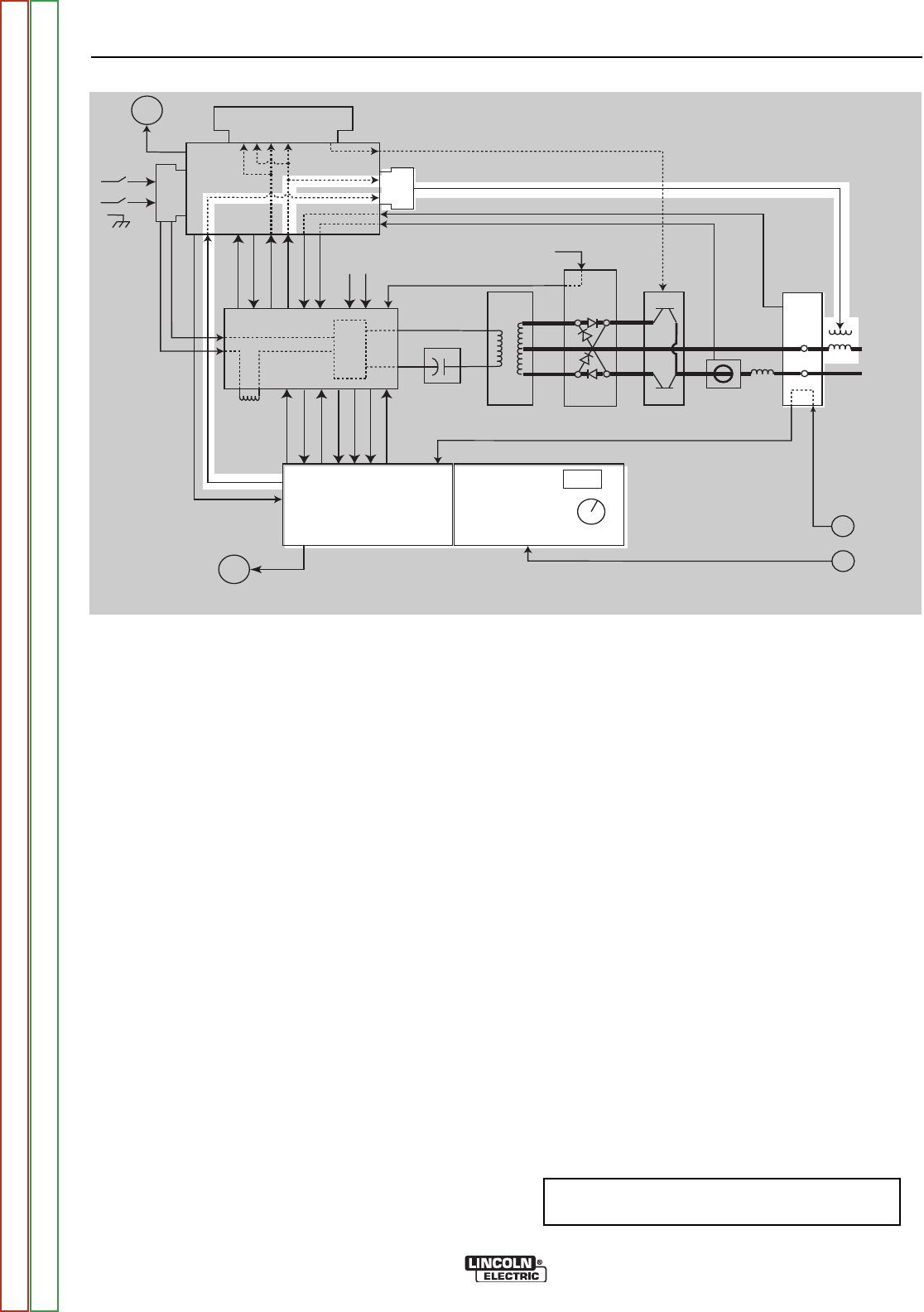
FIGURE E.5 - CONTROL/DISPLAY BOARD, HF BOARD & OUTPUT FILTER BOARD
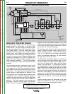
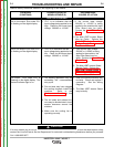
HIGH FREQUENCY (HF) BOARD
The HF Board generates a set of pulses of about 900V,
which are amplified through the high voltage trans-
former to about 8 to 10KV. These pulses that are
repeated at a frequency of about 80HZ are applied to
the high frequency transformer that is located in the
negative welding output leg of the machine. This high
frequency pulse is transferred to the TIG torch via the
high frequency transformer. This allows the remote
starting of the TIG arc without the need for the tungsten
electrode to touch the work. This high frequency pulse
is removed when the welding arc is established.
The command signals are received from the micro-
processor on the Control Board and last for about 1
second maximum. The HF Board receives it’s power
from the + 385 VDC derived from the electrolytic
capacitors on the Main IGBT Inverter Board.
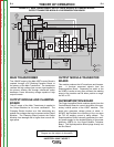
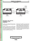
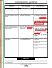
OUTPUT FILTER BOARD
This PC board, located at the welding output terminals
protects the internal circuitry of the machine from high
voltage and high frequency pulses that may be fed
back into the unit via the welding cables, torch cable or
remote control equipment. This unwanted “noise” is
shunted to case ground.
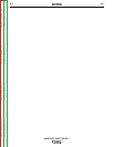
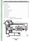
NOTE: Unshaded areas of Block Logic
Diagram are the subject of discussion
Superimposition
board
Bus board
Fan
Input
board
HF
board
Main IGBT
& Power board
4
IGBT's
Control board
Display & LED
board
888
Control
Knob
Gas
Solenoid
DC blocking
capacitor board
Main
Transformer
Output
board
Output
Transistor
Module
Current
Hall
Device
Output
Filter bd.
(bypass)
(D + E)
Remote 2/4
Remote
75, 76, 77
A, B, C
24 VDC Remote 2/4 path (D + E)
turn on AC ckt.
+15, -15, +5
input volt meter
thermostat info
set info
input current meter
turn on PWM
HF control signal
+48, +24
Input
Choke
_
+
RF coil
-48, +24,+15,-15,+5
reconnect info.
voltage feedback
high volt supply
turn on AC ckt.
current feedback
IGBT
Thermostats
Output
Diode
Thermostat
Voltage Feedback
Current Feedback
AC DC Gate drive signals
24 VDC
48 VDC
Output
Choke
Return to Section TOC Return to Section TOC Return to Section TOC Return to Section TOC
Return to Master TOC Return to Master TOC Return to Master TOC Return to Master TOC