


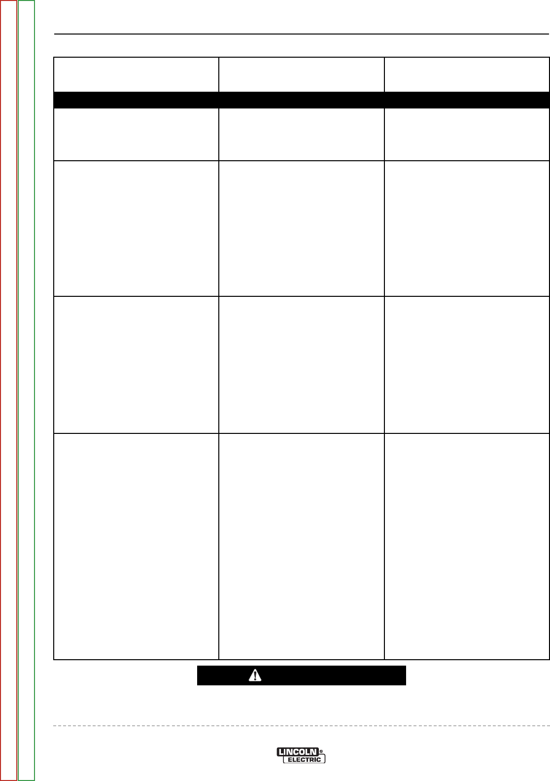
FUNCTION PROBLEMS
Observe Safety Guidelines detailed in the beginning of this manual.
PROBLEMS
(SYMPTOMS)
POSSIBLE AREAS OF
MISADJUSTMENT(S)
RECOMMENDED
COURSE OF ACTION
If for any reason you do not understand the test procedures or are unable to perform the tests/repairs safely,
contact the Lincoln Electric Service Department for technical troubleshooting assistance before you proceed.
Call 1-888-935-3877.
CAUTION
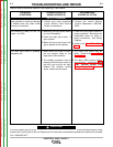
Error code “E20”, “E24”, or “E25” is
flashing on the digital display.
1. Any one of these codes indicates
a memory error.
1. The Control/Display Board is
faulty. Replace.
The machine functions normally
except the cooling fan does not
operate.
1. Check for obstructions that could
prevent the fan from turning.
1. Check the fan fuse F3 located on
the Bus Board Replace if faulty.
2. Perform the Bus Board Test.
3. The Main IGBT Inverter Board
May be Faulty. Perform the
Main IGBT Inverter Board Low
Voltage Supply Test.
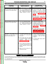
No High Frequency when the torch
trigger is pulled and the machine is
in the TIG mode.
1. Make sure the HF is in the active
mode. See the Set-up Menu in
this manual.
1. Check fuse F2 on the Bus Board.
2. Check for 385VDC at Test
Points 9 and 20. See the Main
IGBT Inverter Board Test.
3. Perform the Control/Display
Board Test.
4. The HF board may be faulty.
Replace.
Error code “E14” is flashing of the
digital display
1. This is an indication that the out-
put inductance is too high.
1. Check for excessive welding
cable length.
2. The Main IGBT Inverter Board
may be faulty.
3. The Superimposition Board may
be faulty.
4. The Control/Display Board may
be faulty.
TROUBLESHOOTING AND REPAIR
F-6 F-6
INVERTEC® V205-T AC/DC™
Return to Section TOC Return to Section TOC Return to Section TOC Return to Section TOC
Return to Master TOC Return to Master TOC Return to Master TOC Return to Master TOC