


THEORY OF OPERATION
E-3 E-3
PRECISION TIG® 225
Return to Section TOC Return to Section TOC Return to Section TOC Return to Section TOC
Return to Master TOC Return to Master TOC Return to Master TOC Return to Master TOC
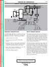
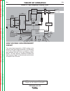
OUTPUT RECTIFICATION AND
FEEDBACK CONTROL
The AC output from the main transformer secondary is
rectified and controlled through the SCR bridge.
Output current is sensed at the shunt as a low voltage
signal and fed back to the control board. The control
board compares the commands of the mode switch,
output control, AC balance control, pulse control, post-
flow control, or remote control with the feedback infor-
mation. The appropriate SCR gate firing signals are
created by the control board and sent to the SCR
bridge. The control board controls the firing of the
SCRs, which control the output of the machine. See
SCR Operation. The control board monitors the ther-
mostats, and also controls the gas solenoid valve, ther-
mal light, auto balance LED, pulse frequency LED, TIG
LED, stick LED, and the digital display.
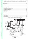
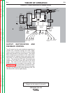
FIGURE E.2 - Output Rectification & Feedback Control
NOTE: Unshaded areas of Block Logic
Diagram are the subject of discussion
INPUT
POWER
SWITCH
MAIN
TRANSFORMER
POLARITY
SWITCH
SCR
BRIDGE
X1
X2
AC
AC
DC+
DC-
CONTROL
BOARD
18VAC
18VAC
115VAC
FAN
REMOTE
RECEPTACLE
H1
H2
H3
SHUNT
115VAC
HIGH VOLTAGE
TRANSFORMER
CIRCUIT
BY-PASS
BOARD
HI-FREQUENCY
TRANSFORMER
C
H
O
K
E
WORK
ELECTRODE
THERMAL
LIGHT
GAS
VALVE
THERMO-
STATS
OUTPUT
CONTROL
MODE
SWITCH
POWER
"ON"
DIGITAL
DISPLAY
F
E
E
D
B
A
C
K
AUTO
BALANCE
LED
TIG
LED
STICK
LED
PULSE
FREQ.
LED
BYPASS
ASBLY
AC
BALANCE
CONTROL
PULSE
CONTROL
POSTFLOW
CONTROL
115 VAC
Receptacle
Circuit Breaker
Protected