


POLARITY SWITCH
REMOVAL AND REPLACEMENT PROCEDURE (continued)
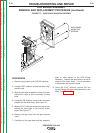
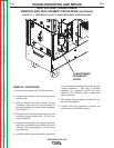
REMOVAL PROCEDURE
1. Remove the input power to the TIG 225
machine.
2. Using the 3/8” nutdriver remove the case wrap-
around cover.
3. Using the 3/32” Allen type wrench remove the
output control knob.
4. Using the Phillips head screwdriver remove the
screw from the polarity switch handle.
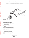
5. With the 2 slot head screwdrivers carefully pry
the polarity switch handle from the shaft.
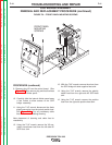
6. Remove the five plastic snap rivets holding the
name plate to the case front. These can be
removed by gently prying at the rivet between
the name plate and the case front.
7. Remove the name plate.
8. With the 1/2” wrench remove the “positive” flex
lead from the polarity switch. See wiring dia-
gram. Label lead and connection point for
reassembly.
9. With the 1/2” wrench remove the “AC” flex lead
from the polarity switch. This lead connects to
the AC plate on the SCR bridge. See wiring
diagram. Label lead and connection point for
reassembly.
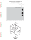
10. Using the 1/2” wrench remove the flex lead
from the rear gang of the polarity switch. This
lead connects to the D1 diode on the SCR
bridge. See wiring diagram. Label lead and
connection point for reassembly.
11. Using the 1/2” wrench remove the flat copper
lead from the polarity switch. This lead con-
nects to the high frequency transformer coil
and the by-pass board. See wiring
diagram. Label lead and connection point for
reassembly.
12. Using the 1/2” wrench remove the other flat
copper lead from the polarity switch. This lead
connects to the lower terminal on the by-pass
board and the “work” lead. See wiring dia-
gram. Label lead and connection point for
reassembly.
13. Using the 1/2” wrench remove the choke lead
from the polarity switch. See wiring diagram.
Label lead and connection point for reassem-
bly.
14. With the 1/2” wrench remove the X1 sec-
ondary lead from the polarity switch. See
wiring diagram. Label lead and connection
point for reassembly.
15. With the 7/16” wrench remove the two nuts
and washers that hold the polarity switch to
the front panel.
16. Carefully rotate the polarity switch assembly to
gain access to the micro-switch.
17. Carefully unsolder the two leads (#311 and
#312) from the micro-switch located on the
polarity switch assembly. See wiring diagram.
Label leads and connection points for
reassembly.
18. Carefully remove the polarity switch assembly
from the machine.
TROUBLESHOOTING AND REPAIR
F-46 F-46
PRECISION TIG® 225
Return to Section TOC Return to Section TOC Return to Section TOC Return to Section TOC
Return to Master TOC Return to Master TOC Return to Master TOC Return to Master TOC