


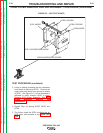

T1 TRANSFORMER TEST (continued)
PROCEDURE
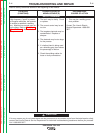
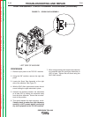
6. If all of the secondary voltages are correct the
T1 transformer is functioning properly.
A. If all of the secondary voltages are missing
or incorrect make certain that the correct
input voltage is being applied to the correct
primary leads. See Table F.1.
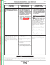
B. If the correct input voltage is being applied to
the primary leads and any or all of the sec-
ondary voltages are incorrect the T1 trans-
former may be faulty. See Main
Transformer and Output Choke Removal
and Replacement. Also check the leads for
broken or loose connections between plugs
J3, J4 and the T1 transformer.
7. Replace case wrap-around cover.
TROUBLESHOOTING AND REPAIR
F-19 F-19
PRECISION TIG® 225
Return to Section TOC Return to Section TOC Return to Section TOC Return to Section TOC
Return to Master TOC Return to Master TOC Return to Master TOC Return to Master TOC
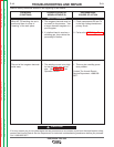
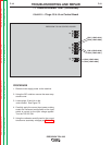
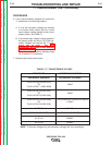
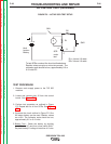
TEST POINTS ACCEPTABLE VOLTAGES
SECONDARY WINDINGS SECONDARY VOLTAGES
PLUG J3 PIN 8 (LEAD #210)
TO 18VAC
PLUG J3 PIN 7 (LEAD #209)
PLUG J3 PIN 4 (LEAD #201)
TO 18VAC
PLUG J3 PIN 3 (LEAD #204)
PLUG J4 PIN 2 (LEAD #260)
CHECK DURING FIRST 5 SECONDS OF POWER UP
TO 115VAC
PLUG J4 PIN 3 (LEAD #232)
X1 TO X2 80 VAC
PRIMARY WINDINGS PRIMARY VOLTAGES
H1 TO H2 208VAC
H1 TO H3 230VAC
TABLE F.1 T1 TRANSFORMER VOLTAGE
NOTE: If the input voltages vary the secondary voltages will vary accordingly.