


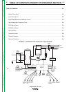
THEORY OF OPERATION
E-5 E-5
PRECISION TIG® 225
Return to Section TOC Return to Section TOC Return to Section TOC Return to Section TOC
Return to Master TOC Return to Master TOC Return to Master TOC Return to Master TOC
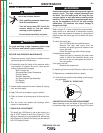
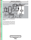
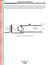
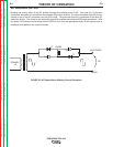
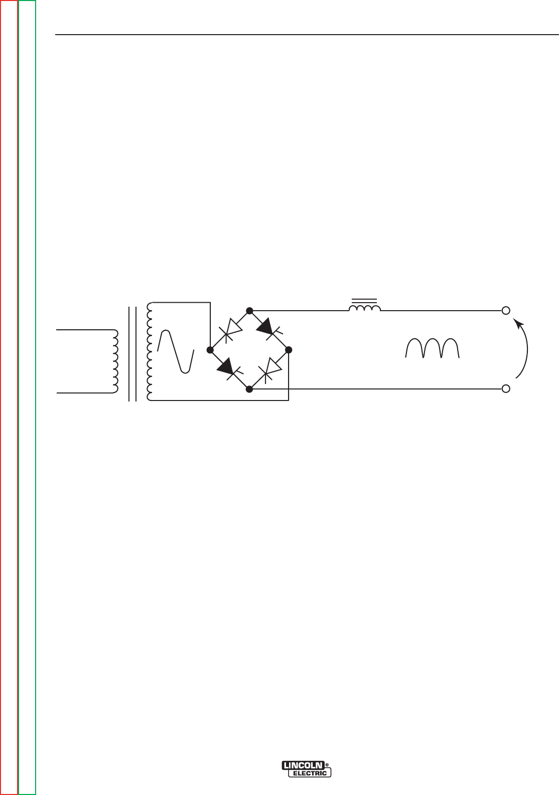
DC WELDING OUTPUT
When the polarity switch is placed in either DC position, the AC voltage from the main transformer secondary is
applied to the SCR bridge. The SCR bridge and choke circuits are connected in a conventional full wave bridge
and filter configuration, resulting in a controlled DC output. Since the choke is in series with the negative leg of
the bridge and also in series with the welding load, a filtered DC is applied to the machine output terminals.
FIGURE E.5 DC Welding Current Generation.
CHOKE
WORK
ELECTRODE
PRIMARY
1Ø
G
G
G
G
DC