


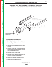

MAIN TRANSFORMER AND OUTPUT CHOKE ASSEMBLY
REMOVAL AND REPLACEMENT PROCEDURE (continued)
REMOVAL PROCEDURE
1. Remove input power to the TIG 225 machine.
2. Perform the SCR Bridge Assembly Removal
Procedure.
3. Unsolder the two 115VAC leads and leads
B231 and B232 from the main transformer
leads. Label leads for reassembly. See wiring
diagram.
4. Unsolder leads W201 and W204 from the main
transformer leads. Label leads for reassembly.
See wiring diagram.
5. Unsolder leads R209 and U210 from the main
transformer leads. Label leads for reassembly.
See wiring diagram.
6. Using the 1/2” wrench remove the shunt
assembly from the choke lead.
7. With the 3/8” wrench remove the H1, H2 or H3
lead from the input power switch. See wiring
diagram. Label the leads and connection points
for reassembly. Cut any necessary cable ties.
8. Remove plug J3 from the control board and
push through the interior divider panel.
9. Using the 1/2” wrench remove the choke lead
from the polarity switch. See wiring diagram.
Label lead and connection point for reassembly.
10. With the 1/2” wrench remove the X1 sec-
ondary lead from the polarity switch. See
wiring diagram. Label lead and connection
point for reassembly.
11. With the 1/2” wrench remove the four nuts and
lock washers from the transformer mounting
bolts at the base of the machine.
12. Carefully hoist the transformer/ choke assem-
bly clear of the base. Clear all leads.
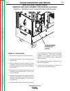
REPLACEMENT PROCEDURE
1. Position the new transformer/choke assembly
onto the base and mounting bolts.
2. Assemble the four nuts and washers to the
mounting bolts on the base of the machine.
3. Assemble the X1 secondary lead to the polarity
switch.
4. Assemble the choke lead to the polarity switch.
5. Install the J3 plug into the control board.
6. Assemble the H1, H2 or H3 lead onto the input
power switch. Insulate and secure the unused
lead (H2 or H3).
7. Assemble the shunt assembly to the choke
lead.
8. Solder leads R209 and U210 to the main trans-
former leads. See wiring diagram. Insulate
connections.
9. Solder leads W201 and W204 to the main
transformer leads. See wiring diagram.
Insulate connections.
10. Solder the two 115VAC leads and leads B231
and B232 to the main transformer leads. See
wiring diagram. Insulate connections.
11. Replace any previously removed cable ties.
Clear leads and check for “shorts” or
“grounds”.
12. Perform the SCR Bridge Assembly
Replacement Procedure.
TROUBLESHOOTING AND REPAIR
F-54 F-54
PRECISION TIG® 225
Return to Section TOC Return to Section TOC Return to Section TOC Return to Section TOC
Return to Master TOC Return to Master TOC Return to Master TOC Return to Master TOC