


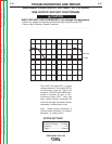

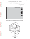
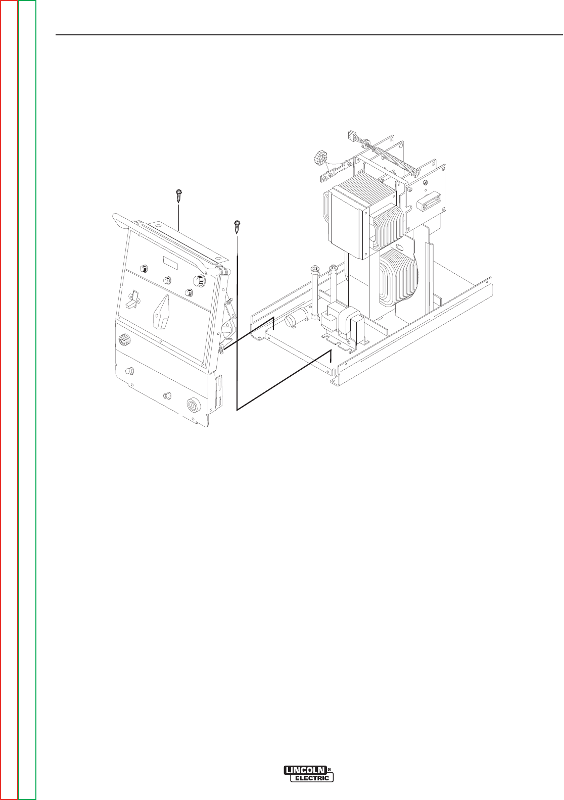
FIGURE F.8 – FRONT PANEL MOUNTING SCREWS
SCR BRIDGE ASSEMBLY
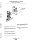
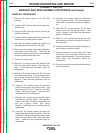
REMOVAL AND REPLACEMENT PROCEDURE (continued)
PROCEDURE (continued)
9. Remove plug J2 from the control board. (See
Figure F.9.) Also remove plug and lead harness
from internal divider panel.
10. Carefully slide the internal divider panel away
a few inches to allow access to the SCR
bridge assembly.
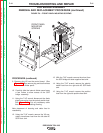
11. Using the 7/16” wrench disconnect the diode
pigtail connection from the polarity switch lead.
See Figure F.10. Cut any necessary cable
ties and remove insulating sleeving.
Note placement of sleeving and cable ties for
reassembly.
12. Using the 7/16” wrench remove the X2 sec-
ondary transformer lead from the left side AC
SCR heat sink.
13. With the 7/16” wrench remove the shunt from
the SCR bridge left side negative heat sink.
14. Using the 7/16” wrench remove the polarity
switch lead from the right side AC SCR heat
sink.
15. Using the 7/16” wrench remove the positive
lead from the right side positive heat sink.
TROUBLESHOOTING AND REPAIR
F-41 F-41
PRECISION TIG® 225
Return to Section TOC Return to Section TOC Return to Section TOC Return to Section TOC
Return to Master TOC Return to Master TOC Return to Master TOC Return to Master TOC
FRONT PANEL
MOUNTING
SCREWS