


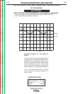
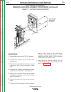
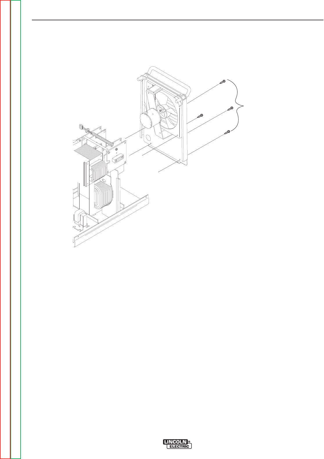
FIGURE F.7 – CASE BACK MOUNTING SCREWS
SCR BRIDGE ASSEMBLY
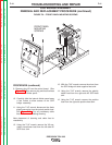
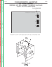
REMOVAL AND REPLACEMENT PROCEDURE (continued)
PROCEDURE
1. Remove input power to the TIG 225 machine.
2. Using the 3/8” nutdriver remove the case wrap-
around cover.
3. With the slot head screwdriver loosen the input
cable strain relief to allow movement of case
back.
4. Using the 3/8” nutdriver remove the two lower
screws from the case back. See Figure F.7.
5. With the 5/16” nutdriver remove the two screws
holding the case back to the internal divider
panel. See Figure F.7.
6. Remove the gas hose from the gas solenoid
valve.
7. Carefully pull the case back and fan assembly
away to allow access to the SCR Bridge
Assembly. Support the case back so as not to
stress the fan motor leads. It is not necessary
to disconnect the fan motor leads.
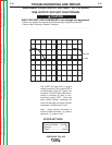
8. Using the 5/16” nutdriver remove the two
screws holding the front panel assembly to the
base. See Figure F.8.
TROUBLESHOOTING AND REPAIR
F-40 F-40
PRECISION TIG® 225
Return to Section TOC Return to Section TOC Return to Section TOC Return to Section TOC
Return to Master TOC Return to Master TOC Return to Master TOC Return to Master TOC
REAR PANEL
MOUNTING
SCREWS