


CASE COVER REMOVAL AND REPLACEMENT PROCEDURE (continued)
TEST PROCEDURE (continued)
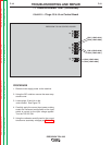
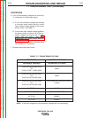
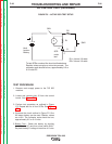
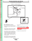
3. Using an analog ohmmeter test the resistance
from anode to cathode of SCR1. Reverse the
meter leads and check from cathode to anode
of SCR1. See Figure F.4. If a low resistance is
indicated in either direction SCR1 is faulty.
Replace SCR Bridge Assembly. See SCR
Bridge Assembly Removal and
Replacement.
4. Repeat Step #3 testing SCR2, SCR3 and
SCR4.
5. The further check the SCR’s functions use an
SCR tester and proceed to the Active SCR
Test.
TROUBLESHOOTING AND REPAIR
F-23 F-23
PRECISION TIG® 225
Return to Section TOC Return to Section TOC Return to Section TOC Return to Section TOC
Return to Master TOC Return to Master TOC Return to Master TOC Return to Master TOC
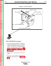
FIGURE F.4 – SCR TEST POINTS
SCR1 ANODE
SCR1 CATHODE/SCR2 ANODE
SCR2 CATHODE
SCR3 CATHODE
SCR4 ANODE
SCR3 ANODE/SCR4 CATHODE