


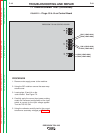
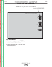
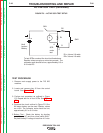

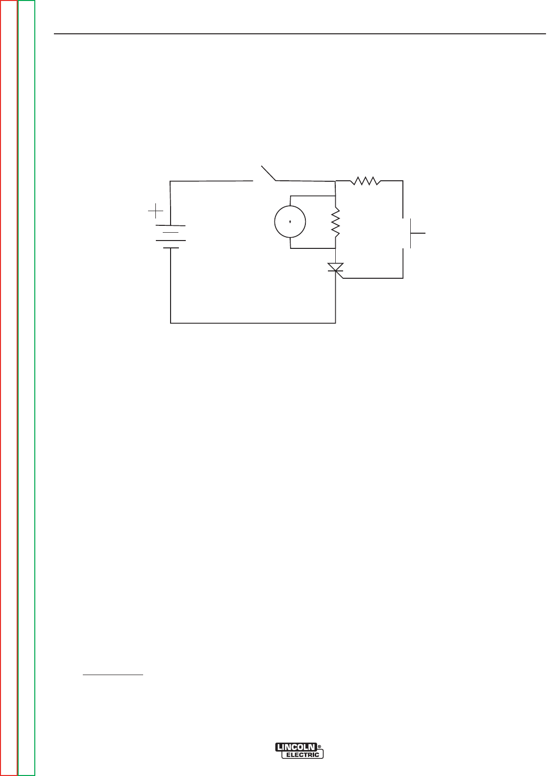
FIGURE F.5 – ACTIVE SCR TEST SETUP
ACTIVE SCR TEST (continued)
TEST PROCEDURE
1. Remove main supply power to the TIG 225
machine.
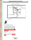
2. Locate and remove plug J2 from the control
board. See Figure F.3.
3. Perform test procedure as outlined in Figure
F.5. Repeat test for all four SCRs. See Figure
F.6.
4. Construct the circuit outlined in Figure F.5. One
6V lantern battery can be used. Resistor values
are ±10%. The voltmeter scale should be low,
approximately 0-5 or 0-10 volts.
5. Battery Test
- Check the battery by shorting
leads (A) and (C) and then close switch SW-1.
Re-place battery if voltage is less than 4.5 volts.
TROUBLESHOOTING AND REPAIR
F-26 F-26
PRECISION TIG® 225
Return to Section TOC Return to Section TOC Return to Section TOC Return to Section TOC
Return to Master TOC Return to Master TOC Return to Master TOC Return to Master TOC
SW1
R2
SW2
R1
A
G
C
V
SCR
under
test
R1= 4 ohms /10 watts
R2= 3 ohms/ 10 watts
6volt
Lantern
Battery
To test SCRs construct the circuit outlined above.
Resistor values are plus or minus ten percent. The
voltmeter scale should be low, approximately 0-5 or
0-10 volts DC.