


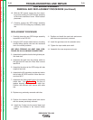


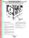
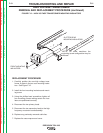


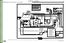

FIGURE F.12 – HIGH VOLTAGE TRANSFORMER MOUNTING INSULATORS
HIGH VOLTAGE TRANSFORMER
REMOVAL AND REPLACEMENT PROCEDURE (continued)
REPLACEMENT PROCEDURE
1. Carefully position the new high voltage trans-
former in place in the two rear mounting insula-
tors. See Figure F.12.
2. Install the front mounting insulators and mount-
ing screw.
3. Using the phillips head screwdriver tighten all
four mounting screws making certain the insu-
lators are positioned correctly.
4. Reconnect the two primary leads.
5. Reconnect the two secondary leads to the high
frequency arc starter board assembly.
6. Replace any previously removed cable ties.
7. Replace the case wrap-around cover.
TROUBLESHOOTING AND REPAIR
F-51 F-51
PRECISION TIG® 225
Return to Section TOC Return to Section TOC Return to Section TOC Return to Section TOC
Return to Master TOC Return to Master TOC Return to Master TOC Return to Master TOC
FRONT MOUNTING
INSULATORS
SLOTTED REAR
MOUNTING INSULATORS
NOTE: On some machines the
mounting screw configuration may be
different.