


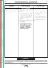
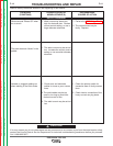
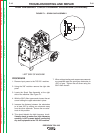
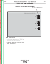
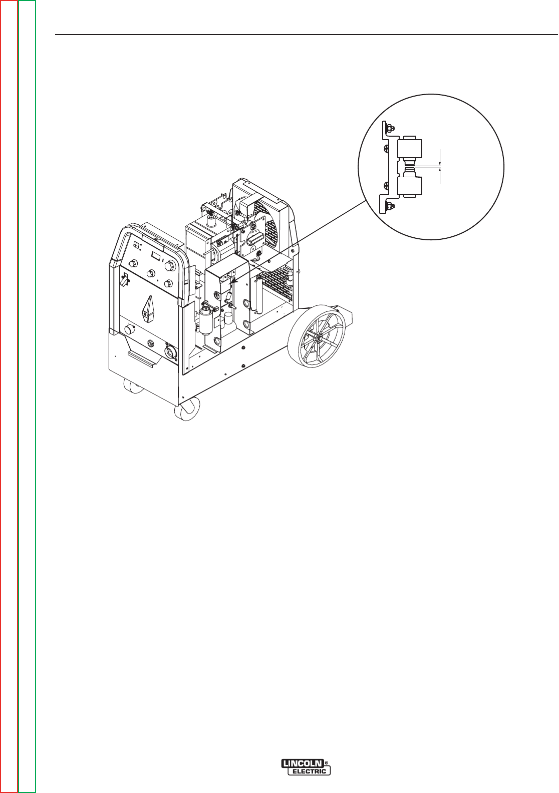
.020 Spark Gap
LEFT SIDE OF MACHINE
FIGURE F.1 – SPARK GAP ASSEMBLY
HIGH FREQUENCY CIRCUIT DISABLE PROCEDURE (continued)
TROUBLESHOOTING AND REPAIR
F-16 F-16
PRECISION TIG® 225
Return to Section TOC Return to Section TOC Return to Section TOC Return to Section TOC
Return to Master TOC Return to Master TOC Return to Master TOC Return to Master TOC
PROCEDURE
1. Remove input power to the TIG 225 machine.
2. Using the 3/8” nutdriver remove the right side
panel.
3. Locate the Spark Gap Assembly at the right
side of the machine. See Figure F.1.
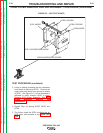
4. With the 5/64” Allen type wrench loosen the set
screw holding the upper electrode in place.
5. Increase the distance between the electrodes
to at least 3/8” by sliding one electrode away
from the other electrode. Secure the one elec-
trode in this position.
6. This should disable the high frequency circuit.
Visually check to make sure high frequency
sparking is NOT present before connecting
any test equipment to the TIG 225 machine.
7. When voltage testing and scope measurements
are complete reset the spark gap electrodes to
.020” air gap. Tighten the set screw using the
5/64” Allen wrench.