


OM-4409 Page 33
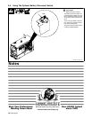
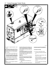
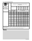
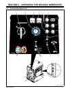
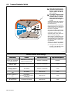
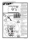
6-2. Description Of Controls (See Section 6-1)
Engine Starting Controls
1 Starting Aid Switch
Use switch to energize starting aid for cold
weather starting.
Push switch up for 60 seconds to operate the
starting aid (intake air heater) before cranking
engine (see starting instructions following).
2 Engine Control Switch
Use switch to start engine, select engine
speed, and stop engine.
In Run position, engine runs at weld/power
speed. In Run/Idle position, engine runs at
idle speed with no generator power or weld
load, and weld/power speed with load ap-
plied.
The air compressor load does not affect en-
gine speed. Run engine at weld/power speed
for maximum air compressor output.
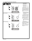
To Start:
. If engine does not start, let engine come
to a complete stop before attempting re-
start.
Above 325 F (05 C): turn Engine Control
switch to Start. Release Engine Control
switch when engine starts.
Below 325 F (05 C) using starting aid
switch:
Turn Engine Control switch to Run/Idle posi-
tion. Push Starting Aid switch up for 60 sec-
onds. While still holding Starting Aid switch,
turn Engine Control switch to Start. Release
Engine Control switch and Starting Aid switch
when engine starts.
To Stop: turn Engine Control switch to Off
position.
Engine/Compressor Gauges
3 Engine Hour Meter
Use gauge to monitor engine running time for
scheduling maintenance.
4 Fuel Gauge
Use gauge to check fuel level. Engine stops
if fuel level is low on units with low fuel shut-
down option.
To check fuel level when engine is not run-
ning, turn Engine Control switch to Run/Idle
position.
5 Air Pressure Gauge
Use gauge to check compressor air pressure.
6 Engine Oil Pressure Gauge
Normal pressure is 30 − 60 psi (206 − 414
kPa). Engine stops if pressure is below 20 psi
(138 kPa).
7 Engine Temperature Gauge
Normal temperature is 212 - 239° F (100 -
115° C). Engine stops if temperature exceeds
270° F (132° C).
8 Battery Voltmeter
Use gauge to check battery voltage and moni-
tor the engine charging system. The meter
should read about 14 volts dc when the en-
gine is running, and about 12 volts dc when
the engine is stopped.
9 Air Compressor Hour Meter (Optional)
Use gauge to monitor compressor running
time for scheduling maintenance.
Weld Controls
10 Process/Contactor Switch
See Section 6-3 for Process/Contactor
switch information.
11 Ampere Range Switch
NOTICE − Do not switch under load.
Use switch to select weld amperage range.
Use all five ranges for Stick welding, and the
lowest four ranges for TIG welding. Read the
upper set of numbers at each range for Stick
welding and the lower set at each range for
TIG welding.
Use the highest range for MIG welding and for
cutting and gouging (CAC-A).
For most welding applications, use lowest
amperage range possible to help prevent arc
outages.
12 Voltage/Amperage Adjust Control
With Process/Contactor switch in any Stick or
TIG setting, use control to adjust amperage
within range selected by Ampere Range
switch. With Process/Contactor switch in any
MIG position, use control to adjust voltage.
With Panel/Remote Switch in Remote posi-
tion, control limits the remote amperage in
TIG mode, but has no effect in Stick and MIG
modes.
Weld output would be about 263 A DC with
controls set as shown (50% of 125 to 400 A).
. The numbers around the Voltage/Amper-
age Adjust control are for reference only
and do not represent an actual percent-
age value.
13 Panel/Remote Switch And Remote 14
Receptacle
Use switch to select front panel or remote
voltage/amperage control. For remote con-
trol, place switch in Remote position and con-
nect remote control to Remote 14 receptacle
RC14 (see Sections 5-10 and 6-4).
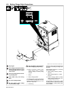
14 Polarity/AC Selector Switch (Optional)
Or Output Selector Switch (Optional)
NOTICE − Do not switch under load.
Use Polarity/AC selector switch to select AC
or DC weld output and DC weld output po-
larity.
Use Output Selector switch to select AC
Weld, DC Weld, or battery charge output (see
Section 8-1).
Weld Meters
15 AC/DC Voltmeter (Optional)
Voltmeter displays voltage at the weld output
terminals, but not necessarily the welding arc
due to resistance of cable and connections.
16 AC/DC Ammeter (Optional)
Ammeter displays amperage output of the
unit.
Air Compressor Controls
17 Air Compressor Switch
Use switch to turn air compressor on and off.
Air pressure is present at the compressor air
shutoff valve whenever the compressor is
running. The compressor shuts off when the
engine stops. To use air, the compressor must
be turned on each time the engine is started.
The air compressor will not start if still under
pressure. If air compressor is turned off, wait
for air pressure to bleed off (about 20 sec-
onds) before turning air compressor on again.
. To extend clutch bearing life, cycle air
compressor off and on once every two
hours during periods of extended use.
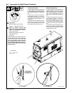
18 Air Shutoff Valve
! Air pressure is present at valve when-
ever Air Pressure Gauge (item 5) indi-
cates air pressure.
Close valve to stop air flow when connecting
or changing tools or air hoses (see Section
5-11).