


OM-4409 Page 57
SECTION 11 − TROUBLESHOOTING
11-1. Troubleshooting Tables
A. Welding
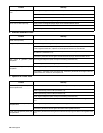
Trouble Remedy
No weld output; generator power output
okay at ac receptacles.
Place Process/Contactor switch in a Weld Terminals Always On position, or place switch in a Remote
On/Off Switch Required position and connect remote contactor to Remote 14 receptacle RC14 (see Sec-
tions 5-10 and 6-1).
Check position of Ampere Range switch.
Check position of optional Output Selector switch (see Section 8-1).
Reset supplementary protector CB11 (see Section 9-8).
Reset supplementary protector CB5 (see Section 9-8). Check for faulty remote device connected to
RC14.
Check and secure connections to Remote 14 receptacle RC14 (see Section 5-10).
Have Factory Authorized Service Agent check connector board PC6 and connections.
Check fuse F2, and replace if open (see Section 9-8). Have Factory Authorized Service Agent check
brushes and slip rings, field excitation circuit, field current regulator board PC1, and the rotor.
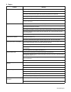
No weld output or generator power
output.
Disconnect equipment from generator power receptacles during start-up.
Check fuses F1 and F2, and replace if open (see Section 9-8). Have Factory Authorized Service Agent
check integrated rectifier SR1, capacitor C9, field current regulator board PC1, and the rotor.
Reset supplementary protector CB12 (see Section 9-8).
Have Factory Authorized Service Agent check brushes and slip rings, and field excitation circuit.
Erratic weld output. Check and tighten connections inside and outside unit.
Be sure connection to work piece is clean and tight.
Use dry, properly stored electrodes.
Remove excessive coils from weld cables.
High weld output. Check position of Ampere Range switch and Voltage/Amperage Adjust control.
Check engine weld/power speed, and adjust if necessary (see Section 9-6).
Have Factory Authorized Service Agent check field current regulator board PC1.
Voltage/Amperage control does not
work when welding in Stick mode.
Place Ampere Range switch in lower range. Voltage/Amperage control does not work with Ampere
Range switch in highest range.
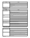
Low weld output. Check engine weld/power speed, and adjust if necessary (see Section 9-6).
Check fuses F1 and F2, and replace if open (see Section 9-8). Have Factory Authorized Service Agent
check integrated rectifier SR1, capacitor C9, field current regulator board PC1, and the rotor.
Electrode sticks to the workpiece more
frequently during low voltage (short arc
length) conditions.
Circuit breaker CB4 may be open. CB4 automatically resets when the fault is corrected (see Section 9-8).
Have Factory Authorized Service Agent check transformer T1 and integrated rectifiers SR4 and SR5.
Have Factory Authorized Service Agent check optional battery charging relay CR7.
Low open-circuit voltage. Check engine weld/power speed, and adjust if necessary.
No remote fine amperage or voltage
control.
Place Panel/Remote Switch in Remote position.
Check and secure connections to Remote 14 receptacle RC14 (see Section 5-10).
Repair or replace remote control device.