


OM-4409 Page 60
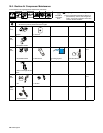
Trouble Remedy
Engine does not run at idle speed. Turn Process/Contactor switch to any position but Remote On/Off Switch Required-TIG.
Check for obstructed throttle solenoid.
Allow circuit breaker CB14 to reset. Have Factory Authorized Service Agent check throttle solenoid TS1
and linkage (see Section 9-8).
Have Factory Authorized Service Agent check idle module PC7, control relays CR3 and CR6, and current
transformer CT1.
Engine uses oil during run-in period;
wetstacking occurs.
Dry engine (see Section 14).
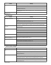
E. Air Compressor
Trouble Remedy
Air compressor does not operate; no air
pressure at air shutoff valve.
Place Air Compressor switch in On position. The air compressor will not start if still under pressure. If
compressor is turned off, wait for air pressure to bleed off (about 20 seconds) before turning compressor
on again.
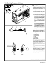
Reset supplementary protector CB15 (see Section 10-4).
Check compressor belt tension. Be sure correct belt is used and is properly installed.
Have Factory Authorized Service Agent check Air Compressor switch S10, control relay CR10, air pres-
sure switch S11, temperature switch S12, compressor control circuit, and air compressor clutch.
Air compressor stops after short period
of operation.
Check compressor oil level (see Section 5-7). Automatic shutdown stops compressor if compressor tem-
perature is too high.
Clean debris from radiator. Automatic shutdown stops compressor if compressor temperature is too high.
Low air pressure. Check for leaks in air lines and hoses.
Adjust compressor air pressure (see Section 10-6).
Check air compressor air cleaner (see Section 10-3).
Have Factory Authorized Service Agent check compressor for rated output.
High air pressure. Adjust compressor air pressure (see Section 10-6).
Be sure control line is connected at regulator valve and inlet valve.
Pneumatic tools freeze up because of
moisture in compressed air.
Install optional air dryer/filter kit (Part No. 195 117).
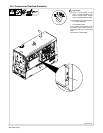
Oil in air from compressor. Check compressor oil level (see Section 5-7). If oil level is too high, system becomes saturated with oil.
Change compressor air/oil separator (see Section 10-5).
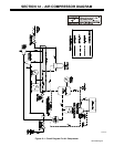
Check connections of control lines (see air compressor circuit diagram in Section 12).
Have Factory Authorized Service Agent check for blocked separator scavenge check valve/filter orifice.
Oil in compressor air cleaner. Have Factory Authorized Service Agent verify compressor inlet valve is operating properly.
F. Optional Battery Charging
Trouble Remedy
No battery charge output; weld output
okay.
Place Output Selector switch in 12 Volt Charge or 24 Volt Charge position.
Check and tighten battery connections if necessary.
Turn on remote control device or turn Process/Contactor switch to any Weld Terminals Always On
position (see Section 6-3).
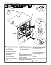
No battery charge or weld output. Disconnect equipment from generator power receptacles during start-up.
Check fuses F1 and F2, and replace if open (see Section 9-8). Have Factory Authorized Service Agent
check integrated rectifier SR1, capacitor C9, field current regulator board PC1, and the rotor.
Reset supplementary protector CB12 (see Section 9-8).
Have Factory Authorized Service Agent check brushes and slip rings, field current regulator board PC1,
and field excitation circuit.