


SECTION
1
-
SAFETY
PRECAUTIONS
AND
SIGNAL
WORDS
1-1.
GENERAL
INFORMATION
AND
SAFETY
1-2.
SAFETY
ALERT
SYMBOL
AND
SIGNAL
AG
I
WORDS
enera
The
following
safety
alert
symbol
and
signal
words
are
Information
presented
in
this
manual
and
on
various
Ia-
used
throughout
this
manual
to
call
attention
to
and
iden
bels,
tags,
and
plates
on
the
unit
pertains
to
equipment
tify
different
levels
of
hazard
and
special
instructions.
design,
installation,
operation,
maintenance,
and
~
This
safety
alert
symbol
is
used
with
the
signal
troubleshooting
which
should
be
read,
understood,
and
words
WARNING
and
CAUTION
to
call
atten
followed
for
the
safe
and
effective
use
of
this
equipment.
tion
to
the
safety
statements.
B.
Safety
WARNING
statements
identify
procedures
or
The
installation,
operation,
maintenance,
and
trouble-
practices
which
must
be
followed
to
avoid
seri
shooting
of
arc
welding
equipment
requires
practices
ous
personal
injury
or
loss
of
life.
and
procedures
which
ensure
personal
safety
and
the
safety
of
others.
Therefore,
this
equipment
is
to
be
in-
CAUTION
statements
identify
procedures
or
stalled,
operated,
and
maintained
only
by
qualified
per-
practices
which
must
be
followed
to
avoid
minor
Sons
in
accordance
with
this
manual
and
all
applicable
personal
injury
or
damage
to
this
equipment.
codes
such
as,
but
not
limited
to,
those
listed
at
the
end
of
Section
1
Safety
Rules
For
Operation
Of
Arc
Weld-
IMPORTANT
statements
identify
special
instructions
ing
Power
Source
in
the
welding
power
source
Owners
necessary
for
the
most
efficient
operation
of
this
equip
Manual.
ment.
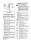
SECTION
2
SPECIFICATIONS
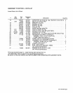
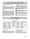
Table
2-1.
SpecIfications
Component
Dimensions
Weight
Height
Width
Depth
Net
Ship
Robot
Interface
22-1/2
in.
(572
mm)
16-1/2in.
(419
mm)
6~1/4in.*
(159
mm)
38
lbs.
(17
kg)
Total
61
lbs.
(27.7
kg)
Gas/Current
Sensing
Control
4-1/2
in.
(108
mm)
5-1/2
in.
(140
mm)
10-1/2
in.
(267
mm)
5
lbs.
(2.3
kg)
Spool
Support
Assembly+
13-3/4
in.
(349
mm)
8-3/4
in.
(222
mm)
8-1/2
in.
(216
mm)
6
lbs.
(2.7
kg)
Add
2-1/4
in.
(57
mm)
for
brake
resistor.
+Spool
Support
without
optional
wire
reel.
*Add
7/8
in.
(22
mm)
for
front
panel
knob.
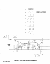
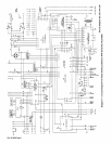
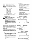
2-1.
DESCRIPTION
and
peak
amperage
or
inductance.
The
robot
interface
control
is
designed
to
interface
with
The
gas/current
sensing
control
contains
the
gas
valve
and
current
sensing
reed
relay.
a
Panasonic
robot
and
an
Arc
Pak
350,
Deltaweld,
Maxtron,
or
Pulstar
450
welding
power
source.
This
unit
These
components
function
with
the
robot
system
when
provides
digital
display
of
weld
volts,wire
feed
speed,
using
the
Gas
Metal
Arc
Welding
(GMAW)
process.
OM-135
582
Page
1