


ERRATA
SHEET
After
this
manual
was
printed,
refinements
in
equipment
design
occurred.
This
sheet
lists
exceptions
to
data
appearing
later
in
this
manual.
AMENDMENT
TO
SECTION
3
INSTALLATION
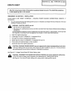
Amend
Section
3-5B.
ROBOT
INTERFACE
-
WELDING
POWER
SOURCE
CONNECTIONS:
REMOTE
17
Connections
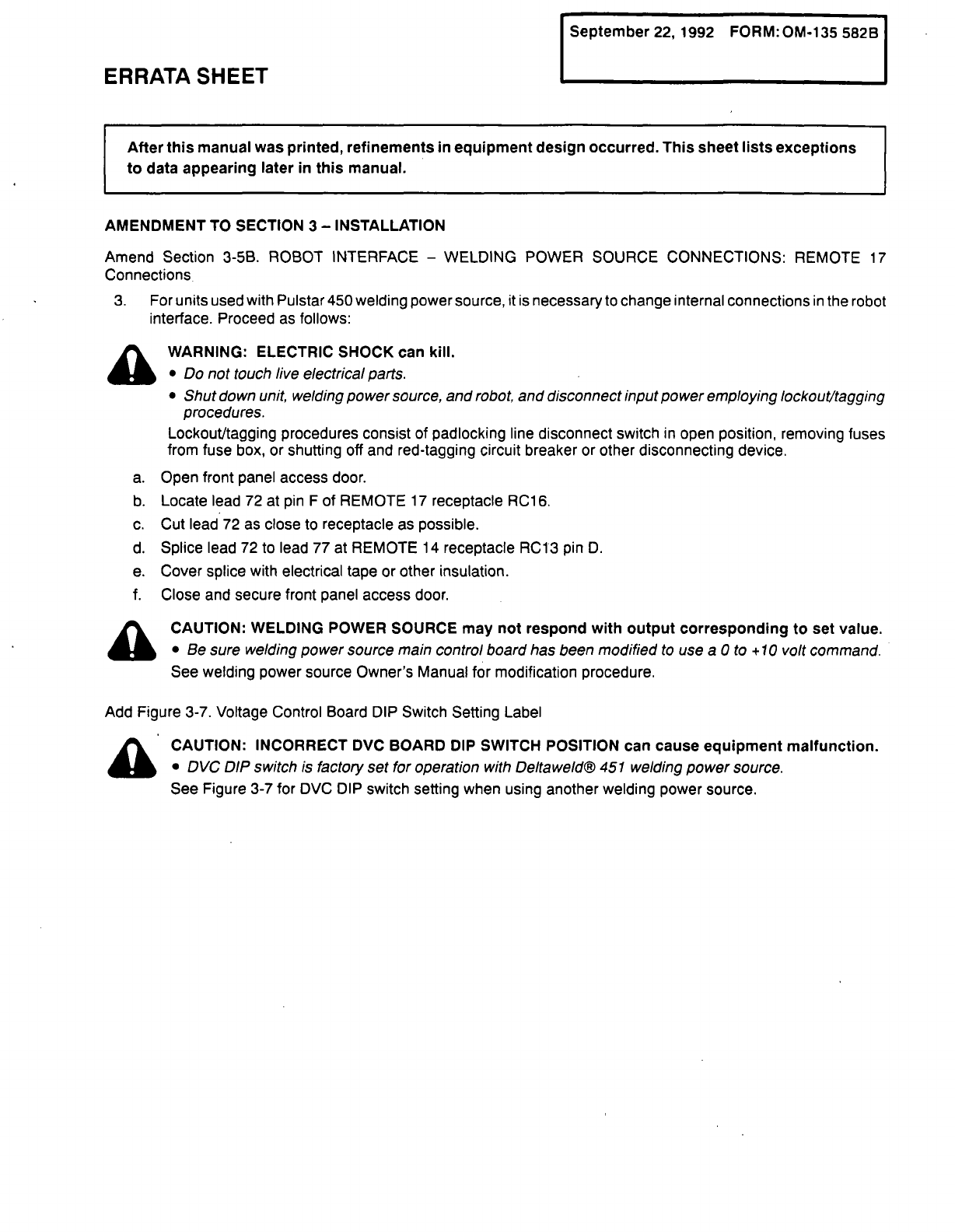
3.
For
units
used
with
Pulstar
450
welding
power
source,
it
is
necessary
to
change
internal
connections
in
the
robot
interface.
Proceed
as
follows:
tk
WARNING:
ELECTRIC
SHOCK
can
kill.
______
Do
not
touch
live
electrical
parts.
Shut
down
unit,
welding
power
source,
and
robot,
and
disconnect
input
power
employing
lockouVtagging
procedures.
Lockout/tagging
procedures
consist
of
padlocking
line
disconnect
switch
in
open
position,
removing
fuses
from
fuse
box,
or
shutting
off
and
red-tagging
circuit
breaker
or
other
disconnecting
device.
a.
Open
front
panel
access
door.
b.
Locate
lead
72
at
pin
F
of
REMOTE
17
receptacle
RC16.
c.
Cut
lead
72
as
close
to
receptacle
as
possible.
d.
Splice
lead
72
to
lead
77
at
REMOTE
14
receptacle
RC13
pin
D.
e.
Cover
splice
with
electrical
tape
or
other
insulation.
f.
Close
and
secure
front
panel
access
door.
a
CAUTION:
WELDING
POWER
SOURCE
may
not
respond
with
output
corresponding
to
set
value.
Be
sure
welding
power
source
main
control
board
has
been
modified
to
use
a
0
to
+
10
volt
command.
See
welding
power
source
Owners
Manual
for
modification
procedure.
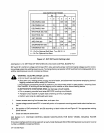
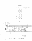
Add
Figure
3-7.
Voltage
Control
Board
DIP
Switch
Setting
Label
a
CAUTION:
INCORRECT
DVC
BOARD
DIP
SWITCH
POSITION
can
cause
equipment
malfunction.
DVC
DIP
switch
is
factory
set
for
operation
with
Delta
weldfi
451
welding
power
source.
See
Figure
3-7
for
DVC
DIP
switch
setting
when
using
another
welding
power
source.