


SECTION
5-
SEQUENCE
OF
OPERATION
Wire
Feed
Speed
0-1OV
=
0-1
000
1PM
Output
Volts
0-1OV
=
0-50V
Peak
Amps
0-1OV
=
0-500
Amps
Output
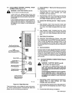
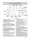
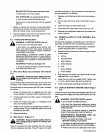
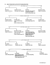
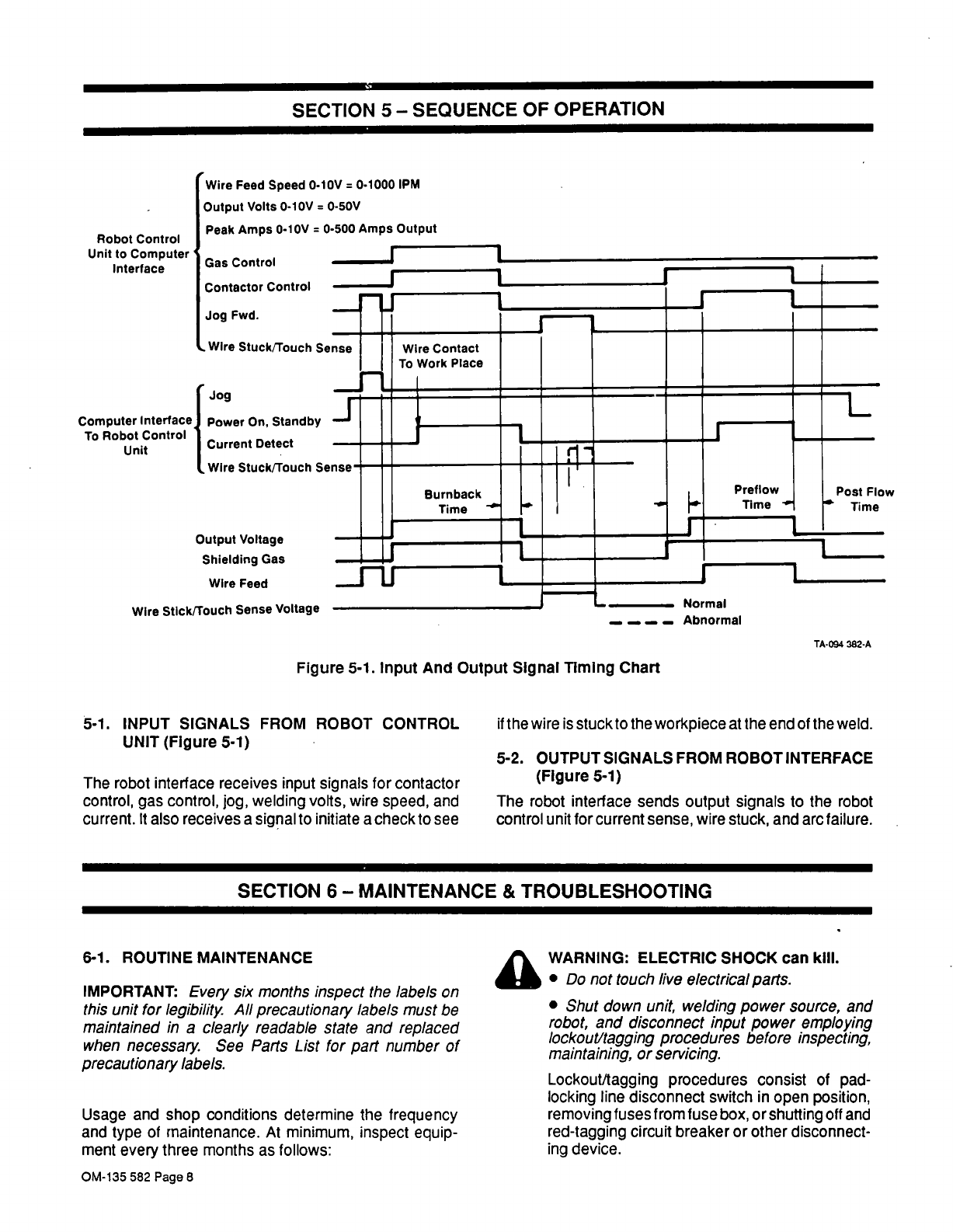
Figure
5-1.
Input
And
Output
Signal
Timing
Chart
5-1.
INPUT
SIGNALS
FROM
ROBOT
CONTROL
UNIT
(Figure
5-1)
The
robot
interface
receives
input
signals
for
contactor
control,
gas
control,
jog,
welding
volts,
wire
speed,
and
current.
It
also
receives
a
signal
to
initiate
a
check
to
see
if
the
wire
is
stuckto
the
workpiece
at
the
end
of
the
weld.
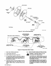
5-2.
OUTPUT
SIGNALS
FROM ROBOT
INTERFACE
(FIgure
5-1)
The
robot
interface
sends
output
signals
to
the
robot
control
unit
for
current
sense,
wire
stuck,
and
arc
failure.
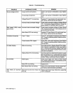
SECTION
6-
MAINTENANCE
&
TROUBLESHOOTING
6-1.
ROUTINE
MAINTENANCE
IMPORTANT:
Every
six
months
inspect
the
labels
on
this
unit
for
legibility.
All
precautionary
labels
must
be
maintained
in
a
clearly
readable
state
and
replaced
when
necessary
See
Parts
List
for
part
number
of
precautionary
labels.
Usage
and
shop
conditions
determine
the
frequency
and
type
of
maintenance.
At
minimum,
inspect
equip
ment
every
three
months
as
follows:
4A
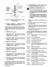
WARNING:
ELECTRIC
SHOCK
can
kill.
Do
not
touch
live
electrical
parts.
Shut
down
unit,
welding
power
source,
and
robot,
and
disconnect
input
power
employing
lockout/tagging
procedures
before
inspecting,
maintaining,
or
servicing.
Lockout/tagging
procedures
consist
of
pad
locking
line
disconnect
switch
in
open
position,
removing
fuses
from
fuse
box,
or
shutting
off
and
red-tagging
circuit
breaker
or
other
disconnect
ing
device.
Robot
control
Unit
to
Computer
Gas
Control
Interface
Contactor
Control
Wire
Stuckilouch
Sense
Output
Voltage
Shielding
Gas
Wire
Stick/Touch
Sense
Voltage
Abnormal
TA-094
382-A
OM-135
582
Page
8