


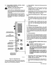

3-8.
WELDING
WIRE
INSTALLATION
(Figure
3-6)
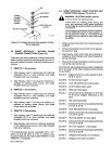
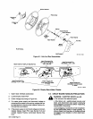
C.
Adjustment
Of
Hub
Tension
(Figure
3-1)
A.
Installation
Of
Spool-Type
Wire
1.
Remove
retaining
ring.
2.
Slide
spool
of
wire
onto
hub
so
that
wire
feeds
oft
bottom
of
spool.
3.
Rotate
spool
until
hole
in
spool
aligns
with
pin
in
hub.
Slide
spool
onto
hub
until
it
seats
against
back
flange
of
the
hub.
4.
Reinstall
retaining
ring
onto
hub.
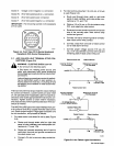
B.
Installation
Of
Optional
Wire
Reel
And
Reel-
Type
Wire
1.
Remove
retaining
ring
and,
if
applicable,
wire
reel
assembly
from
hub.
2.
Lay
wire
reel
assembly
flat
on
a
table
or
floor.
3.
Remove
spanner
nut
from
wire
reel
assembly.
4.
Remove
wire
retainer,
and
install
wire
onto
wire
reel.
Be
sure
that
wire
feeds
off
bottom
of
reel.
5.
Reinstall
wire
retainer
and
spanner
nut
onto
wire
reel.
6.
Slide
wire
reel
assembly
onto
hub,
and
rotate
as
sembly
until
hub
guide
pin
is
seated
in
reel.
7.
Reinstall
retaining
ring
onto
hub.
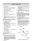
FIgure
3-6.
OptIonal
Wire
Reel
And
Reel-Type
Wire
Installation
Check
the
hub
tension
by
slowly
rotating
the
wire
spool
or
reel.
The
wire
should
unwind
freely,
but
hub
tension
should
be
sufficient
to
keep
wire
taut
and
prevent
back
lash
when
the
wire
feed
stops.
If
adjustment
is
required,
loosen
or
tighten
the
hex
nut
on
the
end
of
the
hub
sup
port
shaft
accordingly.
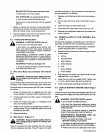
3-9.
BURNBACK
CONTROL
Burnback
is
provided
by
potentiometer
R32
on
Interface
Circuit
Board
PC3
inside
the
unit.
Burnback
can
be
set
between
0
and
0.25
seconds.
The
burnback
circuitry
in
this unit
keeps
the
welding
wire
from
sticking
to
the
workpiece
after
the
arc
is
extin
guished.
The
burnback
circuitry
keeps
weld
output
on
the
welding
wire
from
0
to
0.25
seconds
after
the
wire
has
stopped
feeding.
This
delay
action
permits
the
weld
ing
wire
to
burn
back
to
a
point
where
it
neither
sticks
to
the
workpiece
or
the
contact
tube.
a
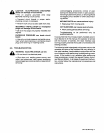
WARNING:
ELECTRIC
SHOCK
can
kill.
Do
not
touch
live
electrical
parts.
Shut
down
unit,
welding
power
source,
and
robot,
and
disconnect
input
power
employing
locko
ut/tagging
procedures
before
inspecting
or
installing.
Lockout/tagging
procedures
consist
of
padlock
ing
line
disconnect
switch
in
open
position,
re
moving
fuses
from
fuse
box,
or
shutting
off
and
red-tag9ing
circuit
breaker
or
other
disconnect
ing
device.
CAUTION:
ELECTROSTATIC
DISCHARGE
(ESD)
can
damage
circuit
boards.
Put
on
properly
grounded
wrist
strap
BEFORE
handling
circuit
boards.
Perform
work
only
at
a
static-safe
work
area.
Retaining
Ring
Retainer
Wire
Reel
/
Spanner
Nut
a
Hub
Support
SC-1V
308
1.
Open
front
access
door
and
locate
PC3.
2.
Locate
potentiometer
R32
in
upper
left
corner
of
PC3.
3.
Rotate
R32
clockwise
to
increase
burnback
time.
4.
Close
and
secure
front
access
door.
OM-135
582
Page
6