


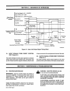
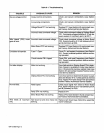
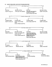
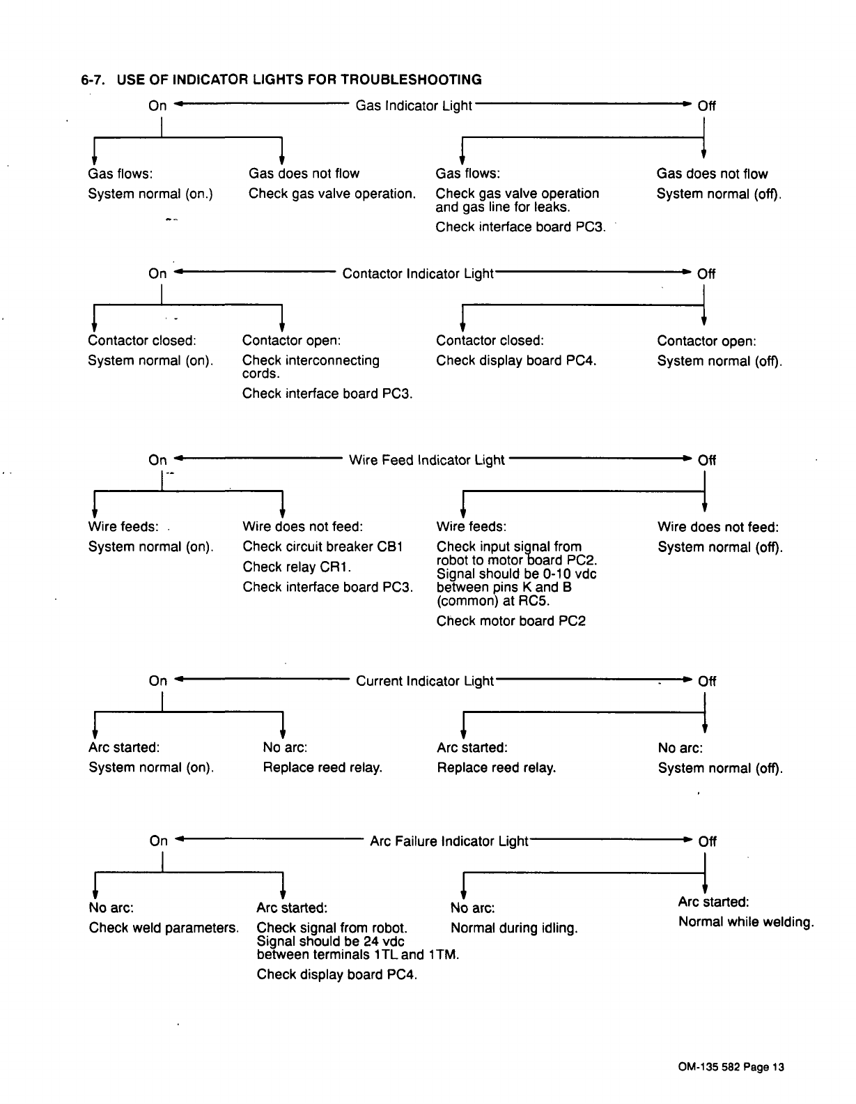
6-7.
USE
OF
INDICATOR
LIGHTS
FOR
TROUBLESHOOTING
Gas
does
not
flow
Check
gas
valve
operation.
Contactor
open:
Check
interconnecting
cords.
Check
interface
board
PC3.
Wire
does
not
feed:
Check
circuit
breaker
CB1
Check
relay
CR1.
Check
interface
board
PC3.
Off
Gas
does
not
flow
System
normal
(off).
~Off
Contactor
open:
System
normal
(off).
Arc
started:
Replace
reed
relay.
No
arc:
System
normal
(off).
~1~
No
arc:
Check
weld
parameters.
On
Gas
Indicator
Light
1~
Gas
flows:
System
normal
(on.)
On
Gas
flows:
Check
gas
valve
operation
and
gas
line
for
leaks.
Check
interface
board
PC3.
Contactor
Indicator
Light
~1~
Contactor
closed:
System
normal
(on).
On
Contactor
closed:
Check
display
board
PC4.
Wire
feeds:
System
normal
(on).
Wire
Feed
Indicator
Light
DOff
Wire
does
not
feed:
System
normal
(off).
Wire
feeds:
Check
input
signal
from
robot
to
motor
board
PC2.
Signal
should
be
0-10
vdc
between
pins
K
and
B
(common)
at
RC5.
Check
motor
board
PC2
~1~
Arc
started:
System
normal
(on).
On
~
Current
Indicator
Light
.
~
Off
No
arc:
Replace
reed
relay.
hr
3
On
~
Arc
Failure
Indicator
Light
~
Off
Jr
Arc
started:
No
arc:
Check
signal
from
robot.
Normal
during
idling.
Signal
should
be 24
vdc
between
terminals
1TL
and
1TM.
Check
display
board
PC4.
3
Arc
started:
Normal
while
welding.
OM-135
582
Page
13