


3-3.
GAS/CURRENT
SENSING
CONTROL
INTER
CONNECTIONS
(Figure
3-2)
a
WARNING:
ELECTRIC
SHOCK
can
kill.
Do
not
touch
live
electrical
parts.
Shut
down
unit,
welding
power
source,
and
robot,
and
disconnect
input
power
employing
lockout/tagging
procedures
before
making
inter
connections.
Lockout/tagging
procedures
consist
of
padlock
ing
line
disconnect
switch
in
open
position,
re
moving
fuses
from
fuse
box,
or
shutting
off
and
red-tagging
circuit
breaker
or
other
disconnect
ing
device.
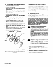
A.
Robot
Interface
Gas/Current
Sensing
Control
Connections
1.
Align
keyways,
insert
14-pin
Amp
plug
into
matching
receptacle
RC9
on
robot
interface,
and
rotate
threaded
collar
fully
clockwise.
2.
Align
keyways,
insert
16-pin
Amp
plug
into
matching
receptacle
RC16
on
gas/current
sensing
control,
and
rotate
threaded
collar
fully
clockwise.
B.
Gas/Current
Sensing
Control
Motor
Connec
tions
1.
Align
keyways,
insert
14-pin
plug
from
motor
cord
into
matching
receptacle
RC7
on
gas/current
sens
ing
control,
and
rotate
threaded
collar
fully
clock
wise.
2.
Align
keyways,
insert
14-socket
plug
from
motor
control
cord
into
matching
free-hanging
receptacle
from
motor,
and
rotate
threaded
collar
fully
clock
wise.
C.
Weld
Cable
Connections
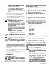
For
Electrode
Positive/Reverse
Polarity,
route
cable
from
welding
power
source
POSITIVE
weld
output
ter
minal,
through
the
gas/current
sensing
control,
to
the
wire
drive
assembly,
and
connect
cable
to
weld
cable
terminal
(see
Motor/Drive
Assembly
Owners
Manual
for
location).
D.
Gas
Connections
Connect
hose
from
gas
regulator/flowmeter
(customer
supplied)
at
gas
source
to
IN
fitting
on
gas/current
sens
ing
control.
Connect
gas
hose
from
wire
drive
assembly
to
fitting
on
gas/current
sensing
control.
The
gas
flow
must
be
accurately
controlled
by
a
regulator/flowmeter
at
the
source.
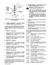
3-4.
VOLTAGE
SENSING
CONNECTIONS
(Figures
3-2
And
3-3)
a
WARNING:
ELECTRIC
SHOCK
can
kill.
Do
not
touch
live
electrical
parts.
Shut
down
unit,
welding
power
source,
and
robot,
and
disconnect
input
power
employing
lockout/tagging
procedures
before
making
inter
connections.
Lockout/tagging
procedures
consist
of
padlock
ing
line
disconnect
switch
in
open
position,
re
moving
fuses
from
fuse
box,
or
shutting
off
and
red-tagging
circuit
breaker
or
other
disconnect
ing
device.
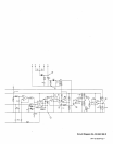
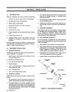
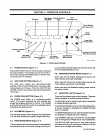
Figure
3-2.
Right
Side
View
TG-tt9
646
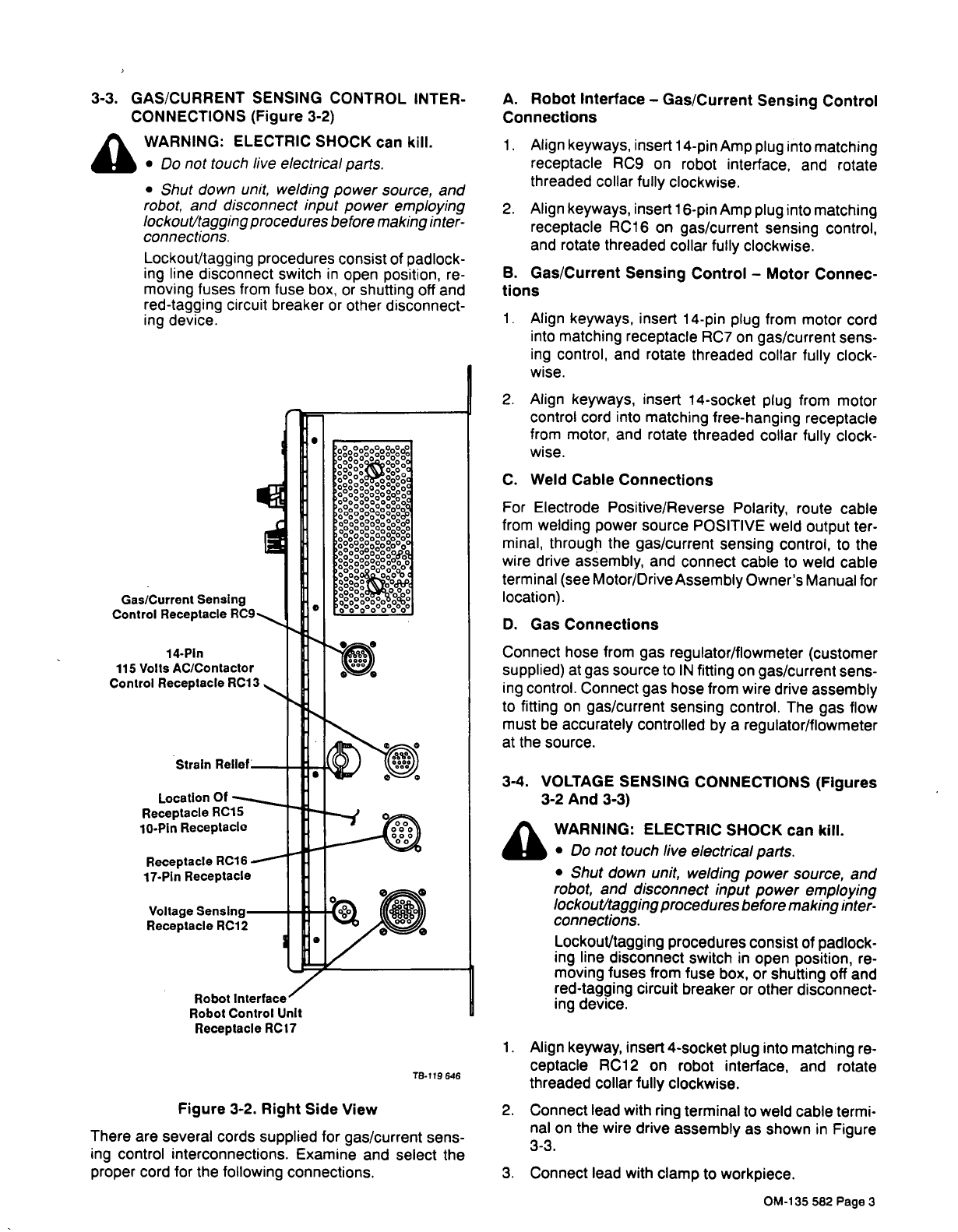
There
are
several
cords
supplied
for
gas/current
sens
ing
control
interconnections.
Examine
and
select
the
proper
cord
for
the
following
connections.
1.
Align
keyway,
insert
4-socket
plug
into
matching
re
ceptacle
RC12
on
robot
interface,
and
rotate
threaded
collar
fully
clockwise.
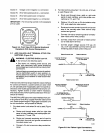
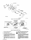
2.
Connect
lead
with
ring
terminal
to
weld
cable
termi
nal
on
the
wire
drive
assembly
as
shown
in
Figure
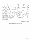
3-3.
3.
Connect
lead
with
clamp
to
workpiece.
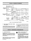
Gas/Current
SensIng
Control
Receptacle
RC9
14-PIn
115
Volts
AC/Contactor
Control
Receptacle
RC13
OM-135
582
Page
3