


MOVING
PARTS
can
cause
serious
injury.
Keep
away
from
moving
parts.
HOT
SURFACES
can
cause
severe
burns.
Allow
cooling
period
before
setvicing.
Maintenance
to
be
performed
only
by
qualified
persons.
1.
Repair
or
replace,
as
required,
all
hose
and
cable;
give
particular
attention
to
frayed
and
cracked
insu
lation
and
areas
where
it
enters
equipment.
2.
Remove
grease
and
grime
from
components;
mois
ture
from
electrical
parts
and
cable.
6-2.
OVERLOAD
PROTECTION
a
WARNING:
ELECTRIC
SHOCK
can
kill.
Do
not
touch
live
electrical
parts.
Shut
down
unit,
welding
power
source,
and
robot,
and
disconnect
input
power
employing
lockout/tagging
procedures
before
inspecting,
maintaining,
or
servicing.
Lockout/tagging
procedures
consist
of
pad
locking
line
disconnect
switch
in
open
position,
removing
fuses
from
fuse
box,
or
shutting
off
and
red-tagging
circuit
breaker
or
other
disconnect
ing
device.
INCORRECT
FUSE
can
damage
unit.
Use
only
replacement
fuse
of
same
size,
type,
and
rating
(see
Parts
List).
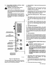
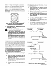
A.
Wire
Drive
Motor
Circuit
Breaker
CB1
(Figure
4-1)
a
WARNING:
Read
and
follow
safety
informa
tion
at
beginning
of
Section
6-2
before
pro
ceeding.
Circuit
breaker
CB1
protects
the
wire
drive
motor
from
overload
.
If
CB1
opens,
the
wire
feed
motor
would
stop.
Should
a
motor
overload
occur
and
CB1
open,
proceed
as
follows:
1.
Check
for
jammed
wire
or
clogged
gun
liner,
and
correct
problem.
If
wire
jams
often,
replace
gun
liner.
2.
If
motor
overload
occurs
often,
repair
or
replace
wire
drive
motor.
3.
Check
for
binding
drive
gear
or
misaligned
drive
rolls,
and
correct
problem.
4.
Reset
circuit
breaker
by
depressing
the
button.
A
cooling
period
may
be
necessary
before
the
circuit
breaker
can
be
reset.
5.
Resume
operation.
B.
Main
Fuse
Fl
(Figure
4-1)
a
WARNING:
Read
and
follow
safety
Informa
tion
at
beginning
of
Section
6-2
before
pro
ceeding.
Fuse
Fl
protects
the
robot
interface
from
an
internal
short
or
excessive
overload.
If
fuse
Fl
opens,
the
robot
interface
shuts
down.
If
the
fuse
opens,
correct
the
prob
lem
and
replace
Fl
as
follows:
1.
Depress
and
rotate
fuse
holder
cover
counterclock
wise.
2.
Pull
out
fuse
with
cover
when
fuse
holder
cover
is
free.
3.
Insert
new
fuse
into
fuse
holder
cover.
4.
Install
fuse
with
fuse
holder
cover
back
into
unit.
5.
Depress
and
rotate
fuse
holder
cover
clockwise
until
cover
is
secure.
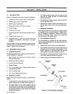
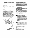
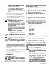
6-3.
REINSTALLATION
OF
HUB
ASSEMBLY
(Fig
ure
6-1)
If
it
becomes
necessary
to
replace
part
or
all
of
the
hub
assembly,
reinstall
the
new
hub
assembly
as
follows:
1.
Remove
hub
assembly
from
hub
support,
and
disas
semble
discarding
worn
or
broken
parts.
2.
Slide
the
following
items
onto
the
hub
support
shaft
in
order
given.
a.
Spring
b..
Keyed
Washer
c.
Fiber
Washer
d.
Brake
Washer
e.
Hub
f.
Brake
Washer
g.
Fiber
Washer
3.
Align
keyway,
and
insert
hub
support
shaft
through
selected
hole
in
hub
support.
4.
Install
hex
nut
onto
hub
support
shaft.
Tighten
hex
nut
until
a
slight
drag
is
felt
while
turning
hub.
5.
Install
welding
wire
according
to
Section
3-8.
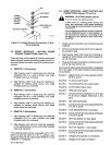
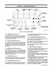
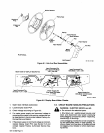
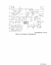
6-4.
DISPLAY
BOARD
PC4
METER
CHECK
(Figure
6-2)
Check
points
are
provided
on
the
display
board
PC4
for
checking
power
supply
and
input
command
for
the
me
ters.
WARNING:
ELECTRIC
SHOCK
can
kill.
Do
not
touch
live
electrical
parts.
Be
sure
that
personnel
performing
testing
procedures
are
familiar
with
and
follow
standard
safety
practices.
Shut
down
unit
before
making
or
changing
meter
or
test
equipment
lead
connections.
ELECTROSTATIC
DISCHARGE
(ESO)
can
damage
electronic
components.
Put
on
a
properly
grounded
wrist
strap
BEFORE
handling
circuit
boards.
Transport
all
static-sensitive
components
in
proper
static-shielding
carriers
and
packages.
Perform
work
only
at
a
static-safe
work
area.
a
OM-135
582
Page
9