


DVC
SWITCH
SETTINGS
S2
Si
1
2
1
2
3
4
5
DELTAWELD
300
ON ON
ON
DELTAWELD
451
0
ON
ON
DELTAWELD
651
0
ON
ON
MAXTRON
300,
400
ON
ON
MAXTRON
450
ON
ON
ON
XMT200/300
ON
ON
ON
ARC
PAK35O
ON
ON
ON
SHOPMASTER
300
ON ON
ON
DIMENSION
400
ON
ON
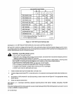
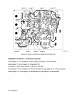
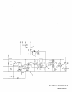
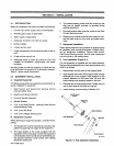
Figure
3-7.
DVC
DIP
Switch
Setting
Label
Add
Section
3-10.
SETTING
DIP
SWITCHES
ON
VOLTAGE
CONTROL
BOARD
PCi
DIP
switch
Si
and
S2
on
voltage
control
board
PCi
allow
setting
the
proper
command
signal
voltage
level
for
control
ling
voltage
output
at
a
welding
power
source.
To
change
factory
set
position
of
DIP
switches
from
a
Deltaweldfi
451
to
another
welding
power
source,
proceed
as
follows:
a
WARNING:
ELECTRIC
SHOCK
can
kill.
Do
not
touch
live
electrical
parts.
Shut
down
unit,
welding
power
source,
and
wire
feeder,
and
disconnect
input
power
employing
lockout/
tagging
procedures
before
setting
DIP
switches.
Lockout/tagging
procedures
consist
of
padlocking
line
disconnect
switch
in
open
position,
removing
fuses
from
fuse
box,
or
shutting
off
and
red-tagging
circuit
breaker
or
other
disconnecting
device.
ELECTROSTATIC
DISCHARGE
(ESD)
can
damage
circuit
boards.
Put
on
properly
grounded
wrist
strap
BEFORE
handling
circuit
boards.
Transport
circuit
boards
in
proper
static-shielding
carriers
or
packages.
Perform
work
only
at
a
static-safe
work
area.
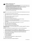
1.
Loosen
screws
securing
front
access
door,
and
open
door.
2.
Locate
voltage
control
board
PCi
in
lower
left
portion
of
component
mounting
panel
inside
robot
interface
con
trol.
3.
Set
position
of
DIP
switches
Si
and
S2
according
to
label
inside
unit
and
Figure
3-7
for
appropriate
welding
power
source.
4.
Close
and
secure
access
door.
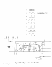
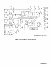
Add
Section
3-11.
VOLTAGE
CONTROL
BOARD
MODIFICATION
FOR
EARLY
MODEL
WELDING
POWER
SOURCE
If
the
robot
interface
control
is
to
be
used
with
an
early
model
Deltaweld
450
or
650
welding
power
source
prior
to
serial
number
JJ400026,
proceed
as
follows:
O
On
For
Optional
Soft
Start.
Turn
Off
Si
-3.
On
For
Optional
Hot
Start.
S~15o864A
OM-135
5828
Page
2