


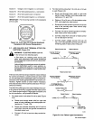
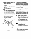

Socket
V:
Voltage
control
negative
()
connection.
Socket
W:
Wire
feed
speed
positive
(+)
connection.
Socket
X:
Wire
feed
speed
wiper
connection.
Socket
Y:
Wire
feed
speed
negative
()
connection.
IMPORTANT:
The
remaining
sockets
in
the
receptacle
are
not
used.
___________________________
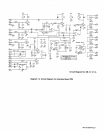
S.0291
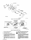
Figure
3-4.
Front
View
Of
24-Socket
Amphenol
Receptacle
With
Socket
Designations
2.
For
robot
control
units
when
115
or
24
vac,
or
24
vdc
is
used
(Figure
3-5):
a.
Route
cord
through
strain
relief
on
right
side
panel
of
robot
interface,
and
make
proper
con
nections
to
1TL
and
1TM.
b.
Obtain
a
115
or
24
vac,
or
24
vdc
isolation
relay
CR1,
and
install
into
robot
control.
c.
Route
and
connect
remaining
end
of
cord
to
one
side
of
the
normally-open
robot
control
relay
contact
and
ground.
d.
Connect
+24
vdc
to
remaining
side
of
normally-
open
robot
control
relay
contact.
e.
Connect
a
lead
from
one
side
of
robot
control
coil
to
weld
alarm
terminal.
f.
Connect
proper
voltage
source
(115
vac,
24
vac,
or
24
vdc)
between
common
terminal
and
remaining
side
of
robot
control
relay
coil.
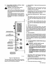
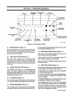
3-7.
ARC
FAILURE
LIGHT
TERMINAL
STRIP
CON
NECTIONS
(Figure
3-5)
j~
WARNING:
ELECTRIC
SHOCK
can
kill.
______
Do
not
touch
live
electrical
parts.
Shut
down
unit,
welding
power
source,
and
robot,
and
disconnect
input
power
employing
lockout/tagging
procedures
before
making
inter
connections.
Lockout/tagging
procedures
consist
of
padlock
ing
line
disconnect
switch
in
open
position,
re
moving
fuses
from
fuse
box,
or
shuthng
off
and
red-tagging
circuit
breaker
or
other
disconnect
ing
device.
(
0
0
Robot
Control
Unit
Robot
Interface
Common
Terminal
Weld
Alarm
Terminal
Ii
So
Equipped
If
So
Equipped
+24V0C
I
Arc
Failure
1TM
Indicator
Light
Robot
Control
Unit
Common
Terminal
Weld
Alarm
Terminal
If
So
Equipped
If
So
Equipped
To
Voltage
Source
(115VAC,
24VAC,
24VDC)
Isolation
Relay
CR1
Robot
Control
Robot
Interface
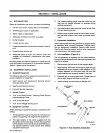
There
are
two
terminal
strips
inside
the
robot
interface
for
control
connections.
Loosen
screws
on
strain
relief
on
unit
right
side
panel
if
applicable,
open
front
panel
ac
cess
door,
and
locate
appropriate
terminal
strip
for
con
nections.
Tighten
screws
on
strain
relief
if
necessary,
and
close
and
secure
front
panel
access
door
when
pro
cedure
is
finished.
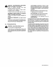
The
ARC
FAILURE
light
on
the
robot
interface
front
pan
el
is
turned
on
and
off
by
a
signal
from
the
robot
control
unit.
Obtain
proper
length
of
18
gauge/2-conductor
cord
for
this
connection,
and
proceed
as
follows:
1.
For
robot
control
units
when
24
vdc
is
used
(Figure
3-5):
a.
Route
cord
through
strain
relief
on
right
side
panel
of
robot
interface,
and
make
proper
con
nections
to
1TL
and
1TM.
b.
Route
and
connect
remaining
end
of
cord
to
weld
alarm
terminal
and
ground
connection
at
the
robot
control
unit.
c.
Connect
+24
vdc
to
common
relay
contact
ter
minal.
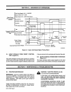
CR1
+24VDC
E-j
Arc
Failure
1TM
Indicator
Light
S-0292
Figure
3-5.
Arc
Failure
Light
Connections
OM-135
582
Page
5