


SECTION
4
OPERATOR
CONTROLS
Gas
Indicator
Light
Contactor
Indicator
Light
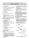
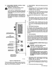
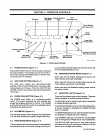
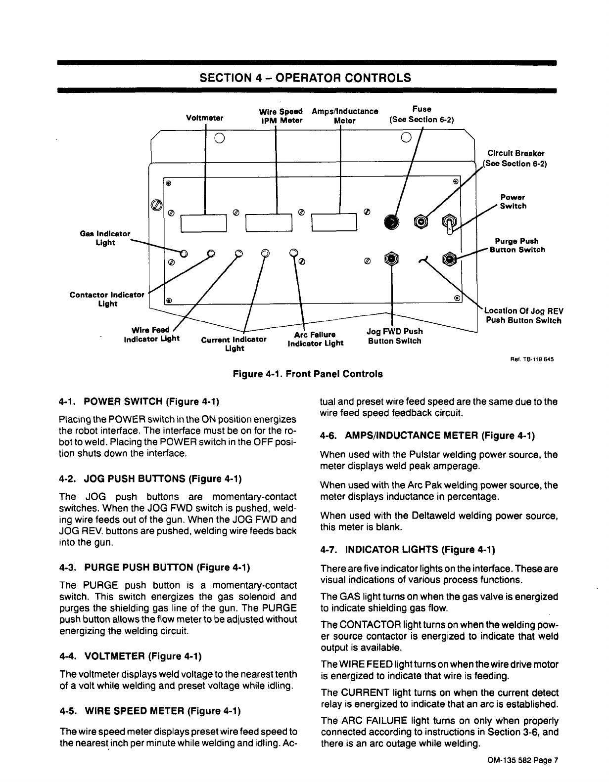
4-1.
POWER
SWITCH
(Figure
4-1)
Placing
the
POWER
switch
in
the
ON
position
energizes
the
robot
interface.
The
interface
must
be
on
for
the
ro
bot
to
weld.
Placing
the
POWER
switch
in
the
OFF
posi
tion
shuts
down
the
interface.
4-2.
JOG
PUSH
BUTTONS
(Figure
4-1)
The
JOG
push
buttons
are
momentary-contact
switches.
When
the
JOG
FWD
switch
is
pushed,
weld
ing
wire
feeds
out
of
the
gun.
When
the
JOG
FWD
and
JOG
REV,
buttons
are
pushed,
welding
wire
feeds
back
into
the
gun.
4-3.
PURGE
PUSH
BUTTON
(Figure
4-1)
The
PURGE
push
button
is
a
momentary-contact
switch.
This
switch
energizes
the
gas
solenoid
and
purges
the
shielding
gas
line
of
the
gun.
The
PURGE
push
button
allows
the
flow
meter
to
be
adjusted
without
energizing
the
welding
circuit.
4-4.
VOLTMETER
(Figure
4-1)
The
voltmeter
displays
weld
voltage
to
the
nearest
tenth
of
a
volt
while
welding
and
preset
voltage
while
idling.
4-5.
WIRE
SPEED
METER
(Figure
4-1)
The
wire
speed
meter
displays
preset
wire
feed
speed
to
the
nearest
inch
per
minute
while
welding
and
idling.
Ac-
Circuit
Breaker
Section
6.2)
Power
Switch
Purge
Push
Button
Switch
Location
Of
Jog
REV
Push
Button
Switch
Ref.
TB-119
645
tual
and
preset
wire
feed
speed
are
the
same
due
to
the
wire
feed
speed
feedback
circuit.
4-6.
AMPS/INDUCTANCE
METER
(Figure
4-1)
When
used
with
the
Pulstar
welding
power
source,
the
meter
displays
weld
peak
amperage.
When
used
with
the
Arc
Pak
welding
power
source,
the
meter
displays
inductance
in
percentage.
When
used
with
the
Deltaweld
welding
power
source,
this
meter
is
blank.
4-7.
INDICATOR
LIGHTS
(Figure
4-1)
There
are
five
indicator
lights
on
the
interface.
These
are
visual
indications
of
various
process
functions.
The
GAS
light
turns
on
when
the
gas
valve
is
energized
to
indicate
shielding
gas
flow.
The
CONTACTOR
light
turns
on
when
the
welding
pow
er
source
contactor
is
energized
to
indicate
that
weld
output
is
available.
The
WIRE
FEED
light
turns
on
when
the
wire
drive
motor
is
energized
to
indicate
that
wire
is
feeding.
The
CURRENT
light
turns
on
when
the
current
detect
relay
is
energized
to
indicate
that
an
arc
is
established.
The
ARC
FAILURE
light
turns
on
only
when
properly
connected
according
to
instructions
in
Section
3-6,
and
there
is
an
arc
outage
while
welding.
Figure
4-1.
Front
Panel
Controls
OM-135
582
Page
7