


SECTION
3INSTALLATION
3-1.
SITE
SELECTION
Select
an
installation
site
which
provides
the
following:
1.
Correct
input
power
supply
(see
unit
nameplate)
2.
Shielding
gas
supply
(if
applicable)
3.
Water
supply
(if
applicable)
4.
Adequate
ventilation
and
fresh
air
supply
5.
No
flammables
6.
A
clean
and
dry
area
7.
Proper
temperature
that
avoids
extremes
of
heat
or
cold
8.
Proper
airflow
around
unit
9.
Adequate
space
to
open
and
remove
cover
and
wrapper
for
installation,
maintenance,
and
repair
functions.
Mounting
holes
provide
the
capability
to
install
and
se
cure
the
system
components
in
a
permanent
location.
Table
2-1
gives
overall
dimensions.
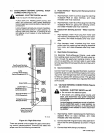
3-2.
EQUIPMENT
INSTALLATION
A.
Supplied
Equipment
The
following
equipment
is
supplied
as
standard
and
re
quires
installation
or
assembly:
1.
Weld
Control
with
Gas/Current
Sensing
Control
Cord
and
Motor
Cord
2.
Gas/Current
Sensing
Control
3.
Hub
and
Spindle
Assembly
4.
Spindle
Support
5.
10
ft.
(3
m)
Weld
Control
Welding
Power
Source
Interconnecting
Cords
6.
lOft.
(3m)
Gas
Hose
7.
10
ft.
(3
m)
Voltage
Sensing
Cord
B.
Equipment
Location
When
deciding
on
equipment
location,
consider
the fol
lowing:
1.
The
equipment
must
be
mounted
to
a
structure
ca
pable
of
supporting
the
weight
of
the
equipment.
2.
The
lead
lengths
of
the
cords
supplied
with
the
equipment
will
limit
the
area
in
which
the
equipment
can
be
located.
Some
cords
can
be
extended
by
us
ing
optional
extension
cords
(check
with
welding
equipment
distributor).
OM-135
582
Page
2
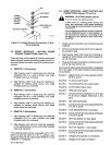
3.
The
interconnecting
cords
must
be
routed
so
that
they
are
not
caught,
pinched,
or
strained
during
welding
operations.
4.
One
weld
output
cable
must
be
routed
to
the
Gas/
Current
Sensing
control.
5.
Welding
wire
must
be
routed
so
that
it
does
not
con
tact
the
weld
control
or
any
other
grounded
equip
ment.
C.
Equipment
Installation
Obtain
appropriate
mounting
brackets
or
adapter
plates
as
necessary
and
mounting
hardware.
Prepare
struc
ture
for
equipment
installation.
Secure
weld
control,
Gas/Current
Sensing
control,
and
all
other
equipment
onto
structures
in
the
welding
area.
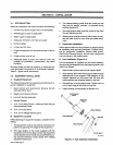
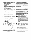
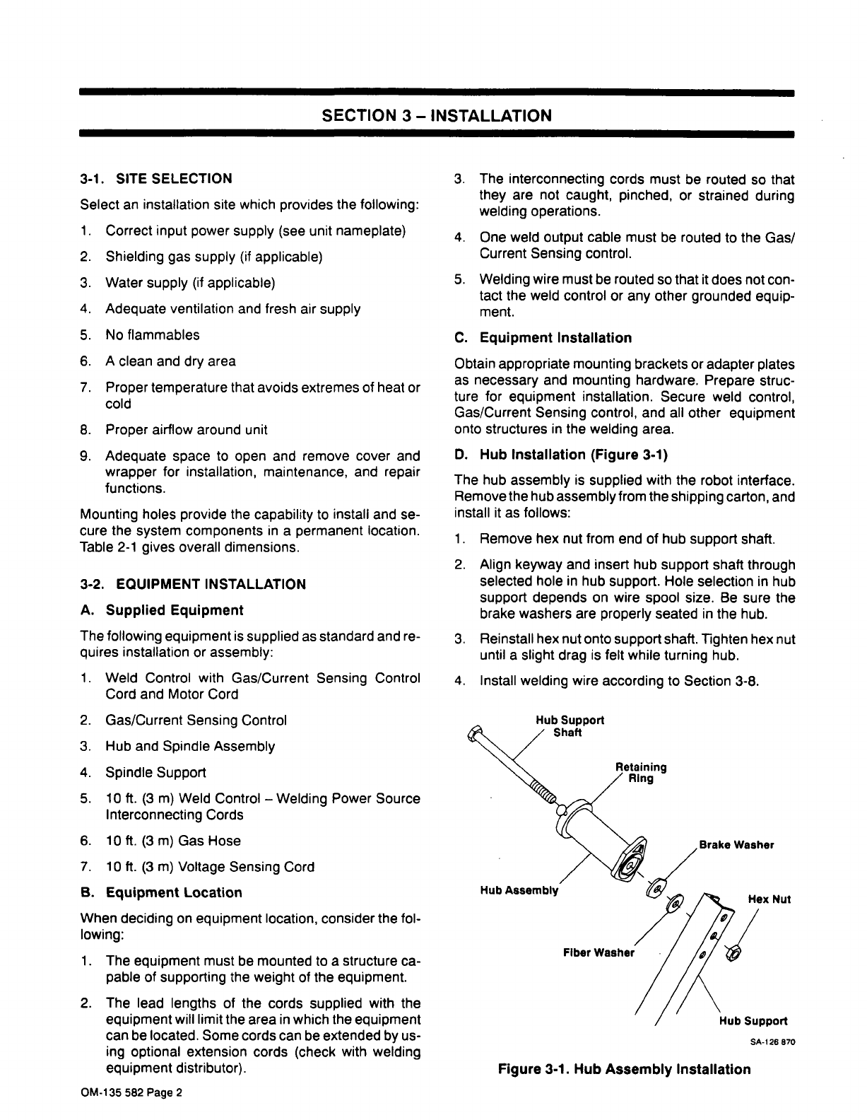
D.
Hub
Installation
(Figure
3-1)
The
hub
assembly
is
supplied
with
the
robot
interface.
Remove
the
hub
assembly
from
the
shipping
carton,
and
install
it
as
follows:
1.
Remove
hex
nut
from
end
of
hub
support
shaft.
2.
Align
keyway
and
insert
hub
support
shaft
through
selected
hole
in
hub
support.
Hole
selection
in
hub
support
depends
on
wire
spool
size.
Be
sure
the
brake
washers
are
properly
seated
in
the
hub.
3.
Reinstall
hex
nut
onto
support
shaft.
Tighten
hex
nut
until
a
slight
drag
is
felt
while
turning
hub.
4.
Install
welding
wire
according
to
Section
3-8.
Hex
Nut
Hub
Support
Shaft
Hub
Assembly
Washer
Hub
Support
SA-126
870
Figure
3-1.
Hub
Assembly
Installation