


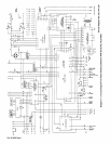

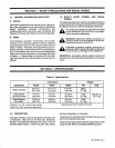
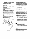
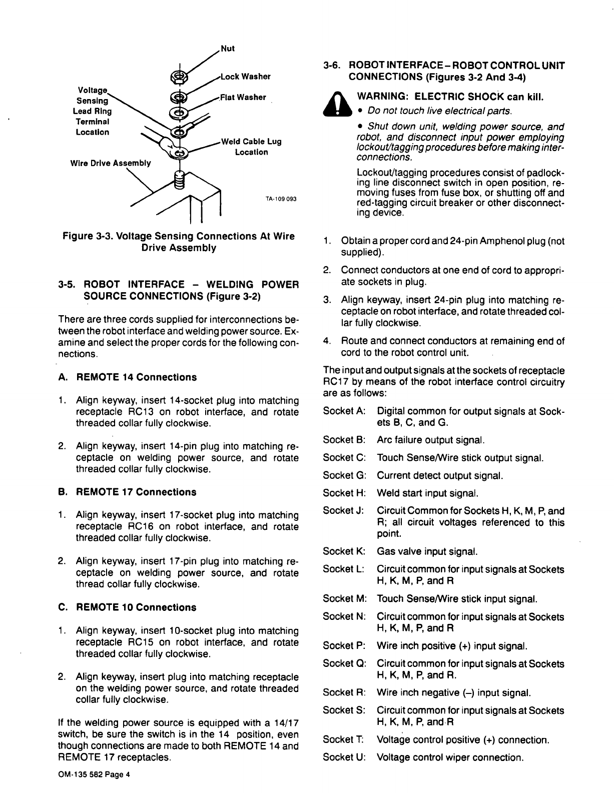
Figure
3-3.
Voltage
Sensing
Connections
At
Wire
Drive
Assembly
3-5.
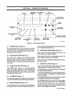
ROBOT
INTERFACE
WELDING
POWER
SOURCE
CONNECTIONS
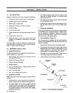
(Figure
3-2)
There
are
three
cords
supplied
for
interconnections
be
tween
the
robot
interface
and
welding
power
source.
Ex
amine and
select
the
proper
cords
for
the
following
con
nections.
A.
REMOTE
14
Connections
1.
Align
keyway,
insert
14-socket
plug
into
matching
receptacle
RC13
on
robot
interface,
and
rotate
threaded
collar
fully
clockwise.
2.
Align
keyway,
insert
14-pin
plug
into
matching
re
ceptacle
on
welding
power
source,
and
rotate
threaded
collar
fully
clockwise.
B.
REMOTE
17
Connections
1.
Align
keyway,
insert
17-socket
plug
into
matching
receptacle
RC16
on
robot
interface,
and
rotate
threaded
collar
fully
clockwise.
2.
Align
keyway,
insert
17-pin
plug
into
matching
re
ceptacle
on
welding
power
source,
and
rotate
thread
collar
fully
clockwise.
C.
REMOTE
10
Connections
1.
Align
keyway,
insert
10-socket
plug
into
matching
receptacle
RC15
on
robot
interface,
and
rotate
threaded
collar
fully
clockwise.
2.
Align
keyway,
insert
plug
into
matching
receptacle
on
the
welding
power
source,
and
rotate
threaded
collar
fully
clockwise.
If
the
welding
power
source
is
equipped
with
a
14/17
switch,
be
sure
the
switch
is
in
the
14
position,
even
though
connections
are
made
to
both
REMOTE
14
and
REMOTE
17
receptacles.
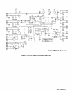
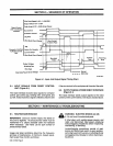
3-6.
ROBOTINTERFACE-ROBOTCONTROLUNIT
CONNECTIONS
(Figures
3-2
And
3-4)
a
WARNING:
ELECTRIC
SHOCK
can
kill.
Do
not
touch
live
electrical
parts.
Shut
down
unit,
welding
power
source,
and
robot,
and
disconnect
input
power
employing
lockout/tagging
procedures
before
making
inter
connections.
Lockout/tagging
procedures
consist
of
padlock
ing
line
disconnect
switch
in
open
position,
re
moving
fuses
from
fuse
box,
or
shutting
off
and
red-tagging
circuit
breaker
or
other
disconnect
ing
device.
1.
Obtain
a
proper
cord
and
24-pin
Amphenol
plug
(not
supplied).
2.
Connect
conductors
at
one
end
of
cord
to
appropri.
ate
sockets
in
plug.
3.
Align
keyway,
insert
24-pin
plug
into
matching
re
ceptacle
on
robot
interface,
and
rotate
threaded
col
lar
fully
clockwise.
4.
Route
and
connect
conductors
at
remaining
end
of
cord
to
the
robot
control
unit.
The
input
and
output
signals
at
the
sockets
of
receptacle
RC17
by
means
of
the
robot
interface
control
circuitry
are
as
follows:
Socket
A:
Digital
common
for
output
signals
at
Sock
ets
B,
C,
and
G.
Arc
failure
output
signal.
Touch
Sense/Wire
stick
output
signal.
Socket
G:
Current
detect
output
signal.
Socket
H:
Weld
start
input
signal.
Socket
J:
Circuit
Common
for
Sockets
H,
K,
M,
P,
and
A;
all
circuit
voltages
referenced
to
this
point.
Socket
K:
Gas
valve
input
signal.
Socket
L:
Circuit
common
for
input
signals
at
Sockets
H,
K,
M,
P,
and
R
Socket
M:
Touch
Sense/Wire
stick
input
signal.
Socket
N:
Circuit
common
for
input
signals
at
Sockets
H,
K,
M,
P~
and
A
Socket
P:
Wire
inch
positive
(+)
input
signal.
Socket
0:
Circuit
common
for
input
signals
at
Sockets
H,
K,
M,
P,
and
R.
Socket
R:
Wire
inch
negative
()
input
signal.
Socket
S:
Circuit
common
for
input
signals
at
Sockets
H,
K,
M,
P,
andR
Voltage
control
positive
(+)
connection.
Voltage
control
wiper
connection.
Nut
Sensing
Lead
Ring
Terminal
Location
Cable
Lug
Location
TA-109
093
Socket
B:
Socket
C:
Socket
T:
Socket
U:
OM.135
582
Page
4