


a
WARNING:
ELECTRIC
SHOCK
can
kill.
Do
not
touch
live
electrical
parts.
Shut
down
unit,
welding
power
source,
and
wire
feede~
and
disconnect
input
power
employing
Iockout/
tagging
procedures
before
making
circuit
board
modifications.
Lockout/tagging
procedures
consist
of
padlocking
line
disconnect
switch
in
open
position,
removing
fuses
from
fuse
box,
or
shutting
off
and
red-tagging
circuit
breaker
or
other
disconnecting
device.
ELECTROSTATIC
DISCHARGE
(ESD)
can
damage
circuit
boards.
i
Put
on
properly
grounded
wrist
strap
BEFORE
handling
circuit
boards.
Transport
circuit
boards
in
proper
static-shielding
carriers
or
packages.
Perform
work
only
at
a
static-safe
work
area.
IMPORTANT:
A
customer-supplied
cord
(Miller
#042562)
is
required
to
connect
the
welding
power
source
to
the
weld
control.
1.
Loosen
screws
securing
front
access
door,
and
open
door.
2.
Locate
voltage
control
board
PCi
in
lower
left
portion
of
component
mounting
panel
inside
robot
interface
con
trol.
3.
Mark
and
disconnect
leads
from
voltage
control
board
PCi.
4.
Mark
and
disconnect
plugs
from
PCi.
5.
Note
position
of
circuit
board
and
remove
from
unit.
6.
Place
circuit
board
on
a
stationary
work
surface
so
that
component
side
is
facing
up.
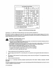
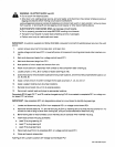
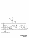
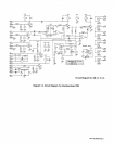
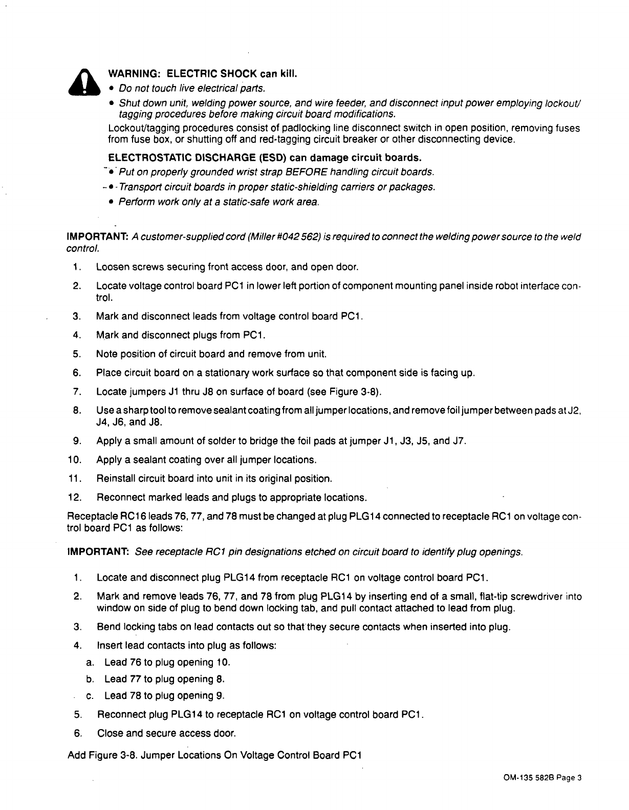
7.
Locate
jumpers
Ji
thru
J8
on
surface
of
board
(see
Figure
3-8).
8.
Use
a
sharp
tool
to
remove
sealant
coating
from
all
jumper
locations,
and
remove
foil
jumper
between
pads
at
J2,
J4,
J6,
and
J8.
9.
Apply
a
small
amount
of
solder
to
bridge
the
foil
pads
at
jumper
Ji, J3,
J5,
and
J7.
10.
Apply
a
sealant
coating
over
all
jumper
locations.
11.
Reinstall
circuit
board
into
unit
in
its
original
position.
12.
Reconnect
marked
leads
and
plugs
to
appropriate
locations.
Receptacle
RC1
6
leads
76,
77,
and
78
must
be
changed
at
plug
PLG1
4
connected
to
receptacle
RC1
on
voltage
con
trol
board
PCi
as
follows:
IMPORTANT:
See
receptacle
RC1
pin
designations
etched
on
circuit
board
to
identify
plug
openings.
1.
Locate
and
disconnect
plug
PLG14
from
receptacle
RC1
on
voltage
control
board
PCi.
2.
Mark
and
remove
leads
76,
77,
and
78
from
plug
PLG1
4
by
inserting
end
of
a
small,
flat-tip
screwdriver
into
window
on
side
of
plug
to
bend
down
locking
tab,
and
pull
contact
attached
to
lead
from
plug.
3.
Bend
locking
tabs
on
lead
contacts
Out
50
thatthey
secure
contacts
when
inserted
into
plug.
4.
Insert
lead
contacts
into
plug
as
follows:
a.
Lead
76
to
plug
opening
10.
b.
Lead
77
to
plug
opening
8.
c.
Lead 78
to
plug
opening
9.
5.
Reconnect
plug
PLG14
to
receptacle
RC1
on
voltage
control
board
PCi.
6.
Close
and
secure
access
door.
Add
Figure
3-8.
Jumper
Locations
On
Voltage
Control
Board
PCi
OM-1355828Page3