


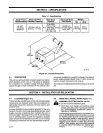
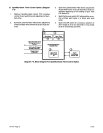


Figure
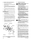
4-2. Typical
RegulatorlFlowmeter
Installation
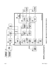
4-5.
14-PIN
PLUG CONNECTION
(Figures
4-3
And
4-4)
The
14-pin
plug
PLG1
00,
on
the
end of
the
interconnect
-
ing
cord,
provides
a
junction
point
for
connecting
the
wire
feeder
to
a
welding
power
source.
This
connection
provides
24
volt
ac
power,
and
contactor
control when
used
with
a
constant
voltage
(CV)
power
source
with
a
14-pin
receptacle.
To
make
connections,
align
keyway,
insert
plug,
and
rotate
threaded
collar
fully
clockwise.
The
pins
on
plug
PLG
100
are
defined
in
relation
to
both
the
power
source
and
wire
feeder.
The
welding
power
source
provides
six
functions
to
the
wire
feeder.
The
pins
are
designated as
follows:
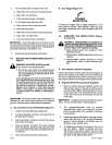
Pin
A:
Up
to
10
amperes
of
24
volts
ac,
60
Hz,
with
re
-
spect
to
socket
G (circuit
common);
protected by
fuse
in
welding
power
source.
Pin
B:
24
volts ac
input
power
to
energize
the
weld
con
-
tactor.
The
feeder
sends
back
24
volts ac by
means
of
a
contact closure
from pin A
to
pin
B.
Pin
G:
24
volts ac
circuit common;
also connected
to
welding
power
source
chassis.
IMPORTANT:
The
remaining
pins
in
the
receptacle are
not
used
by
the
feeder.
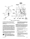
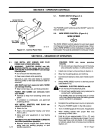
Shielding
Gas
valve
Fitting,
14-Pin
Plug
Gas
cylinder
Valve
Argon
or
Argon
Mix
cylinder
SB-109
492
Ref.
S-0004
Figure
4-4. Front
View
Of
14-Pin
Plug
With
Pin
Locations
4-6.
WELDING
WIRE
INSTALLATION
(Figure
4-5)
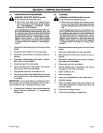
A
WARNING: ELECTRIC
SHOCK
can kill.
•
Do
not
touch
live
electrical
parts.
•
Shut
down
wire
feeder and
welding
power
source,
and
disconnect
input
power
em
ploy
-
ing
lockout/tagging
procedures
before
work
-
ing
on
feeder.
Lockout/tagging
procedures
forwire
feeder
con
-
sist
of
disconnecting
interconnecting
cord,
and
for
welding
power
source consist
of
padlocking
line
disconnect
switch
in open
position,
remov-
ing
fuses
from
fuse
box,
or shutting
off and
red-
tagging
circuit
breaker
or
other
disconnecting
device.
Stop
engine, and
disconnect
negative
(—)
battery cable
from battery
on
welding
gen
-
erators.
A
CAUTION: LOOSE
WELDING
WIRE can
cause
Injury.
•
Keep
a
firm
hold
on
the
wire
during
installa
-
tion,
removal,
and
threading
operations.
Spooled wire
has
a
tendency
to
unravel
rapidly
when
loosened
from
the
spool.
SA-125
924
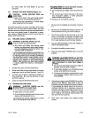
IMPORTANT:
If
it should become
necessary
to
replace
any
part of
the
hub
assembly
see
hub
assembly
rein
-
stallation instruction
in
Section
10-3.
Flow
Adjustment
CO
2
Washer
CO2
cylinder
CO2
Installation
Argon
Installation
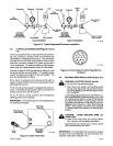
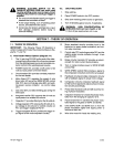
Wire
Feed
Weld
Cable
Connection
Opening
Figure
4-3.
Rear
Panel
View
TM-1571
Page
6
5-21E