


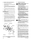
5.
For
50
Series
style
one-piece
drive
rolls:
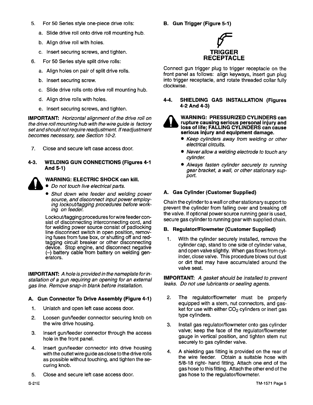
B.
Gun
Trigger (Figure 5-1)
a.
Slide
drive
roll
onto
drive
roll
mounting
hub.
b.
Align
drive
roll
with
holes.
c.
Insert
securing
screws, and tighten.
6.
For
50
Series
style
split
drive
rolls:
a.
Align holes
on
pair of split
drive
rolls.
b.
Insert
securing
screw.
c.
Slide
drive
rolls
onto
drive
roll
mounting
hub.
d.
Align
drive
rolls
with
holes.
e.
Insert
securing
screws, and tighten.
IMPORTANT:
Horizontal
alignment
of
the drive
roll
on
the drive
roll
mounting
hub
with
the
wire
guide
is
factory
set
and
should
not
require
readjustment.
If
readjustment
becomes
necessary,
see
Section 10-2.
7.
Close
and
secure
left
case
access
door.
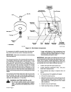
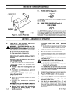
4-3.
WELDING
GUN
CONNECTIONS
(Figures
4-1
And
5-1)
A
WARNING:
ELECTRIC
SHOCK
can kill.
•
Do
not
touch
live
electrical
parts.
•
Shut
down
wire
feeder
and
welding
power
source,
and
disconnect
input
power
employ
-
ing
lockout/tagging
procedures
before
work
-
ing
on
feeder.
Lockout/tagging
procedures
for
wire feeder
con
-
sist
of
disconnecting
interconnecting
cord,
and
for
welding
power
source consist
of
padlocking
line
disconnect switch
in open
position,
remov-
ing
fuses
from
fuse box,
or shutting
off
and red-
tagging circuit
breaker
or
other
disconnecting
device.
Stop
engine, and
disconnect
negative
(—)
battery
cable
from
battery
on
welding
gen
-
erators.
IMPORTANT:
A
hole
ispro
vided
in
the
nameplate
form-
stallation
of
a
gun
requiring an
opening
for
an
external
gas
line.
Remove snap-in
blank
before
installation.
A.
Gun
Connector
To
Drive
Assembly
(Figure 4-1)
1.
Unlatch and
open
left
case
access
door.
2.
Loosen
gun/feeder
connector securing
knob
on
the
wire
drive
housing.
3.
Insert
gun/feeder connector
through
the
access
hole
in
the
front
panel.
4.
Insert
gun/feeder
connector
into
drive
housing
with
the
outlet
wire
guide
as
close
to
the
drive
rolls
as
possible
without touching,
and
tighten
the
se
-
curing
knob.
5.
S-21E
Close and
secure
left
case
access
door.
‘9=
TRIGGER
RECEPTACLE
Connect
gun
trigger plug
to
trigger receptacle
on
the
front
panel
as
follows:
align
keyways,
insert
gun
plug
into
trigger
receptacle,
and
rotate
threaded
collar
fully
clockwise.
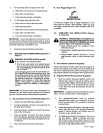
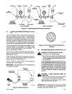
4-4.
SHIELDING
GAS
INSTALLATION
(Figures
4-2
And
4-3)
A
WARNING:
PRESSURIZED
CYLINDERS can
rupture
causing serious
personal
injury
and
loss
of
life;
FALLING
CYLINDERS
can
cause
serious
injury
and
equipment
damage.
•
Keep
cylinders
away
from
welding
or
other
electrical circuits.
•
Never
allow
a welding
electrode
to
touch
any
cylinder.
•
Always fasten
cylinder
securely
to
running
gear
bracket,
a
wall,
or
other
stationary
sup-
port.
A.
Gas
Cylinder (Customer
Supplied)
Chain
the
cylinder
to
a
wall or
other
stationary
support
to
prevent
the
cylinder
from
falling
over
and
breaking
off
the
valve.
If
optional
power
source
running
gear is
used,
secure gas
cylinder
to running
gear
with
supplied
chain.
B.
Regulator/Flowmeter
(Customer
Supplied)
1.
With
the
cylinder
securely
installed,
remove
the
cylinder
cap,
stand
to one
side
of
cylinder
valve,
and
open
valve
slightly.
When
gas
flows
from
cyl
-
inder,
close
valve.
This procedure
blows
out
dust
or
dirt
that
may
have
accumulated
around
the
valve
seat.
IMPORTANT:
A
gasket should
be
installed
to
prevent
leaks.
Do
not
use
lubricants
or
sealing
agents.
2.
The
regulator/flowmeter
must
be
properly
equipped with
a
stem,
nut
connectors,
and
gas
-
ket
for
use
with
either
CO
2
cylinders
or
inert
gas
type
cylinders.
3.
Install
gas
regulator/flowmeter onto
gas
cylinder
valve;
keep
the
face
of
the
regulator/flowmeter
gauge
in
vertical
position,
and
tighten
stem
nut
securely
to
gas
cylinder
valve.
4.
A
shielding
gas fitting
is
provided
on
the
rear of
the
wire
feeder.
Obtain
a
suitable
hose
with
5/8-18
right- hand
fitting.
Attach
one end of
the
gas
hose
to
this
fitting.
Attach the
other
end of
the
gas
hose
to
the
regulator/flowmeter.
TM-1571
Page
5