


SECTION
8—
TROUBLESHOOTING
A
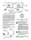
8-1.
TESTING
INSTRUMENTS
AND
INFORMA
-
TION
The
service procedures
in
this
manual
require
proper
testing
instruments.
Use
a
good quality
digital
volt-
ohmmeter
(DVM)
with
one
megohm
input
impedance
or
greater
and
diode
check capability
(use
an
analog VOM
for
variable
resistor
testing). If
an
oscilloscope
is
speci
-
fied,
use
a
good
quality
unit
with
one
megohm
input
im
-
pedance
or
greater.
If a
circuit
board
has
a protective
coating,
it
will
be
necessary
to remove
coating
or
use
needle probes
in
the
test
area
to
obtain
proper
contact.
Recoat
areas
if
necessary
to retain
corrosion
protection.
Digital
volt-ohmmeters
(DVM’s)
do
not
require
lead
po
-
larity attention
when making connections.
However,
the
meter
may
indicate
a
—
(negative)
voltage
when
the
test
procedure specified
a
+
(positive) voltage.
If
the
incor
-
rect
polarity
appears
on
the
display, reverse
meter
lead
connections
to
test
points.
8-2.
CIRCUIT
BOARD
HANDLING
PRECAUTIONS
WARNING:
ELECTRIC
SHOCK
can
kill.
•
Do
not
touch live
electrical
parts.
•
Shut
down
wire
feeder
and
welding
power
source,
and
disconnect
input
power
employ
-
ing
lockout/tagging
procedures
before
inspecting,
maintaining,
or
servicing.
Lockout/tagging procedures
forwirefeedercon
-
sist
of
disconnecting
interconnecting
cord,
and
for
welding
power
source
consist
of
padlocking
line
disconnect switch
in
open
position,
remov
-
ing
fuses
from
fuse box,
or
shutting
off
and
red-
tagging
circuit
breaker
or
other
disconnecting
device.
Stop
engine,
and
disconnect
negative
(—)
battery
cable
from
battery
on
welding
gen
-
erators.
MOVING
PARTS
can
cause serious
injury.
•
Keep
away
from
moving
parts.
HOT
SURFACES
can
cause
severe burns.
•
Allow
cooling
period
before servicing.
CAUTION:
ELECTROSTATIC
DISCHARGE
(ESD)
can
damage
circuit
boards.
•
Put
on
properly
grounded
wrist
strap
BEFORE
handling
circuit
boards.
•
Transport
circuit
boards
in
proper
static-
shielding
carriers
or
packages.
•
Perform
work
only
at
a static-safe
work
area.
INCORRECT
INSTALLATION
or
misaligned
plugs
can
damage
circuit board.
•
Be
sure
that
plugs
are
properly
installed
and
aligned.
EXCESSIVE
PRESSURE
can
break
circuit
board.
•
Use
only
minimal pressure and
gentle
move
-
ment
when
disconnecting
or
connecting
board
plugs
and
removing
or
installing
board.
A
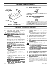
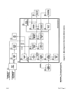
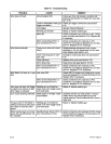
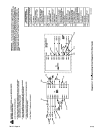
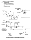
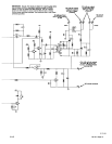
8-3.
TROUBLESHOOTING
(Table
8-1
And
Dia
-
gram
8-1)
A
WARNING:
ELECTRIC
SHOCK
can
kill.
•
Do
not
touch
live
electrical
parts.
•
Shut
down
wire
feeder
and
welding
power
source,
and
disconnect
input
power
employ
-
ing
lockout/tagging
procedures
before
inspecting,
maintaining,
or
servicing.
Lockout/tagging procedures
forwire
feeder
con-
sist
of
disconnecting
interconnecting
cord,
and
for
welding
power source consist
of
padlocking
line
disconnect
switch
in
open
position,
remov
-
ing
fuses
from
fuse box,
or
shutting
off
and
red-
tagging
circuit
breaker
or
other
disconnecting
device.
Stop
engine,
and
disconnect negative
(—)
battery
cable
from
battery
on
welding
gen
-
erators.
MOVING
PARTS
can
cause
serious
injury.
•
Keep away
from
moving
parts.
HOT
SURFACES
can
cause
severe
burns.
•
Allow
cooling
period
before servicing.
Troubleshooting
to
be
performed
only
by
qualified
persons.
The
troubleshooting
table
is
designed
to
diagnose some
of
the
troubles
that
can
develop
in
this
wire
feeder.
Any
circuit
normally
tied
to
ground must
be
at
ground
poten
-
tial.
Use
the table
in
conjunction
with the
diagrams
in
this
manual
and
the exploded
views
and
component
values
in
the
Service
Parts Manual
while performing
tro
-
ubleshooting
procedures.
When replacing
components,
use
only
genuine
MILLER
replacement
parts.
MILLER parts
are
required
for
war-
ranty
repair by
authorized
warranty
service
agency.
Resistance
and
continuity
measurements
must
be
made
with the
unit
shut
down.
Isolate
components
be-
fore
making
resistance
and
continuity
measurements.
IMPORTANT:
Before beginning troubleshooting
proce
-
dures,
visually
examine
internalcomponents
for
signs
of
overheating
and
failure.
Many
major problems,
such
as
winding(s) failure
are
usually
apparent
by
discoloration,
smoke,
and
smell.
Fortunately
most
elect
rical
pro
blems
are
relatively
simple:
blown
fuses,
tripped
circuit
break
-
ers,
incorrect
switch positions, loose
connections,
cor
-
rosion,
and
the
like.
A
complete,
careful
inspection
often
saves
considerable
time,
money
and
frustration.
IMPORTANT: Be
sure
that
all connections
are
correct
and
secure according
to Section
4
and
that
all
controls
and
switches
are
in
proper
positions
before
proceeding
with
troubleshooting.
TM-1571 Page
14
S-21E