


be
made
when
the
wire
feeder
is
put
into
operation.
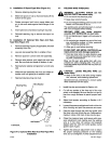
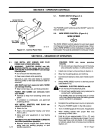
4-8.
ADJUST
THE
HUB
TENSION
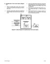
(Figure 4-1)
A
CAUTION: LOOSE
WELDING
WIRE can
:ause
Injury.
Keep
a
firm
hold
on
the wire
during
installa
-
tion,
removal,
and
threading
operations.
Spooled
wire
has
a
tendency
to
unravel
rapidly
when
loosened from
the
spool.
Check
the
hub
tension
by
slowly
pulling
the
wire
toward
the
drive
roll.
The
wire
should
unwind
freely,
but have
sufficient
tension
to
keep the
wire
taut and
prevent
back
-
lash
when
wire
feeding
stops.
If
adjustment
is
neces
-
sary,
loosen or
tighten
the
hex
nut
on
the
end of
the
hub
support
shaft
accordingly.
4-9.
WELDING
CABLE
CONNECTION
A
WARNING: ELECTRIC
SHOCK
can
kill.
•
Do
not
touch
live
electrical
parts.
•
Shut
down
wire
feeder and
welding
power
source,
and
disconnect
input
power
employ
-
ing
lockout/tagging
procedures
before
mak
-
ing
weld
cable
connections.
Lockout/tagging
procedures
forwire
feedercon
-
sist
of
disconnecting
interconnecting
cord,
and
for
welding
power
source
consist
of
padlocking
line
disconnect switch
in
open
position,
remov
-
ing
fuses
from
fuse box,
or
shutting
off
and
red-
tagging
circuit
breaker
or
other
disconnecting
device.
Stop
engine,
and
disconnect negative
(—)
battery
cable
from
battery
on
welding
gen
-
erators.
1.
Unlatch and
open
left
case
access
door.
2.
Route
weld
cable
through weld
cable
connection
opening
on
rear
of
unit
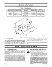
(see
Figures
4-1
and
4-3).
3.
Connect
end of
cable
to
terminal
on
bottom
of
drive
assembly.
Be
sure
that
terminal
is
clean
and
bolt
is
secure.
4.
Close and
secure
left
case
access
door.
4-10.
FEEDING WELDING
WIRE
A
WARNING: ELECTRIC
SHOCK
can kill;
MOVING
PARTS
can
cause
Injury.
•
Do
not
touch
live
electrical
parts.
•
Keep
away
from
pinch
points.
•
Do
not
energize
welding
powersource
or
wirE
feeder
until
instructed
to
do
so.
The
welding
wire
and
all
metal
parts
in
contaci
with
it
are
energized
while
welding.
WELDING
WIRE
can
cause
puncture
Wounds;
HOT
SURFACES
can
burn skin.
•
Do
not
depress
gun
trigger until
instructed
to
do
so.
•
Do
not
point
gun
toward
any
part of
the
body
any
conductive
surface,
or
other personnel
when threading
welding
wire.
•
Allow
gun
to
cool
before
touching.
1.
Be
sure
wire
is
installed
as
instructed
in
Section
4-7.
2.
Be
sure
gun
is
installed
according
to Section
4-3
of
this
manual
and
the
gun
Owner’s
Manual.
3.
Cut
off
any
portion
of
the
free
end of
the
wire
which
is
not straight.
If
necessary,
straighten
wire
to remove cast.
Be
sure
that
the
cut
end
is
free
from
rough
surfaces
to
permit proper
feeding.
4.
Lay
gun
cable
assembly
out flat
and
straight
(no
coils
in
the
cable/conduit).
5.
Energize the
welding
power
source.
6.
Place
the
wire
feeder POWER switch
in
the
ON
position.
A
WARNING: ELECTRIC
SHOCK
can kill;
TAN
-
GLED
WELDING
WIRE can
touch
case
caus-
ing Welding power
source
open-circuit
volt
-
age
to
be
present
on
case
if
gun
trigger
is
pressed.
•
Do
not
touch
wire
feeder
case
if
gun
trigger
is
pressed,
and
wire does
not
feed.
•
If
wire
stops
feeding,
tum
off
welding
power
source,
and
determine
the
cause.
•
Correctanyhub
tension,
jammed
wire,
or
gun
liner
damage
problems
before
trying
to
con-
tinue
welding.
7.
Press
the
gun
trigger
(see
WARNING block
at
be
-
ginning
of
the Section).
Wire feeds
if
drive
roll
pressure
is
properly
adjusted
to
prevent
slippage.
If
wire
slippage
is
noticed,
adjust
hub
tension
ac
-
cording
to
Section
4-8.
If
excessive
pressure
is
required,
check
gun
contact
tube
and gun
liner
for
correct
size
or
obstructions.
Release
the
trigger
when
welding
wire extends
approximately
one
inch
(25
mm)
out
of
gun tip.
8.
Shut
down
wire
feeder
and
welding
power
source.
TM-1571 Page
8
S-21E