


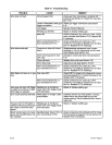

WARNING: ELECTRIC
SHOCK
can kill;
TANGLED
WELDING
WIRE can
touch
case
causing
welding
power
source
open-circuit
voltage
to
be
present
on
case
if
gun
trigger
is
pressed.
•
Do
not
touch
wire
feeder
case
if
gun
trigger
is
pressed
and
wire does
not
feed.
•
If
wire
stops
feeding,
turn
off
welding
power
source,
and
determine
the
cause.
•
Correctanyhub
tension,jammed
wire,
or
gun
liner
damage
problems
before
trying
to
continue
welding.
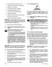
6-2.
SHUTTING
DOWN
1.
Stop
welding.
2.
Place
POWER switch
in
the
OFF
position.
3.
Shut
down
welding
power
source
or
generator.
4.
Turn
off
shielding
gas
at
source,
if
applicable.
A
WARNING: HIGH
CONCENTRATION
OF
SHIELDING
GAS
can
harm health
or
kill.
•
Shut
off
gas
supply
when
not
in
use.
SECTION
7-
THEORY
OF
OPERATION
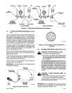
7-1.
THEORY
OF
OPERATION
IMPORTANT:
The
following
Theory
Of
Operation
is
written
in
steps
which
match
the
circled
numbers
on
Dia-
grams
7-1
and
7-2.
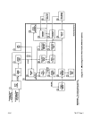
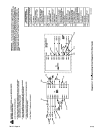
Wire
Feeder
Without
Options
(Diagram 7-1)
The
14-pin
plug PLG100
on
the
end of
the
inter
-
connecting cord
provides
24
volts ac
input
power
from
the
welding
power
source
and
provides
con-
tactor
control
to
the
welding
power
source.
2.
POWER switch
51
provides
on/oft
control
of
24
volts ac
input
power
to
the
wire
feeder.
3.
Circuit
breaker
CB1
provides
overload
protection
for
the
wire
feeder.
4.
Motor
Board
PCi
regulates
the speed
of
wire
drive
motor
Ml
as
set
by
WIRE
SPEED
control
R32.
PCi
also
controls
gas
valve
051
and
weld-
ing
power
source
contactor
via
control relay
CR1.
5.
Gas
valve
051
provides
shielding
gas
during
the
weld
cycle.
6.
Integrated
rectifier
SRi
converts
the
24
volts ac
input
power
to
a
rectified
35
volts
dc.
Capacitor
Cl
provides
filtering
for
the
35
volts
dc.
Voltage regulator
VR1
reduces the
35
volts dc
in
-
put
voltage
to
24
volts dc
for
control
circuitry
on
PCi
and
trigger
receptacle
RC1
01.
9.
Trigger receptacle
RC1
01
provides
the
trigger
in
-
put signal
to
the
motor
stop/start
circuitry.
A.
1.
7.
8.
10.
Motor
stop/start
circuitry
provides
input
to
the
brake turn
on
ramp,
phase modulation,
and
con-
trol relay circuitries.
11.
Control
relay
CR1
controls
gas
valve
051
and
the
welding
power
source
contactor
through
14-pin
plug
PLG100.
12.
Brake
circuitry
transistor
Q7
provides
an
electri
-
cal
path
for
motor
current
during
braking.
13.
Turn
on
ramp
provides
power
to
WIRE
SPEED
control
R32.
14.
WIRE
SPEED
control
R32
provides
a
signal
to
the
comparator circuitry
to
control the
wire
speed.
15.
Feedback circuitry
provides
comparator circuitry
with
a feedback
signal
of
actual
motor
voltage.
16.
Comparator circuitry compares feedback
signal
to
R32
control signal
and
adjusts
phase
modula
-
tion
circuitry
accordingly.
17.
Phase
reset
transistors
Q5
and
Q6 reset the
tim
-
ing
of
phase modulation.
18.
Unijuction
transistor
Qi
creates
the phase
modu
-
lation
from
the
charging of
capacitor ClO.
19.
Pulse
transformer
Ti
transfers
the phase
modu
-
lated
signal
to
the
gates
of
SCRi
and SCR2.
20.
Drive
SCR’s
SCRi
and
SCR2
turn
on
from
the
phase
modulation
signal
and
supply
power
to
wire
drive
motor
Mi.
21.
Wire
drive
motor
Ml
feeds
the
welding
wire.
A
TM-1571
Page
10
S-21E