


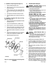

A.
Installation
Of
Spool-Type
Wire
(Figure 4-1)
4-7.
WELDING
WIRE
THREADING
1.
Remove
retaining
ring
from
hub.
2.
Slide
wire
spool
on
hub
so
that
wire
feeds
off
the
bottom
of
the
spool.
3.
Rotate
wire
spool
until
hole
in spool
slides
over
pin
in
hub and
seats
against back
flange
of
the
hub.
4.
Insert optional
compression spring
if
required.
5.
Reinstall retaining
ring
to
secure
wire
spool
on
hub.
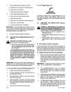
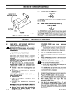
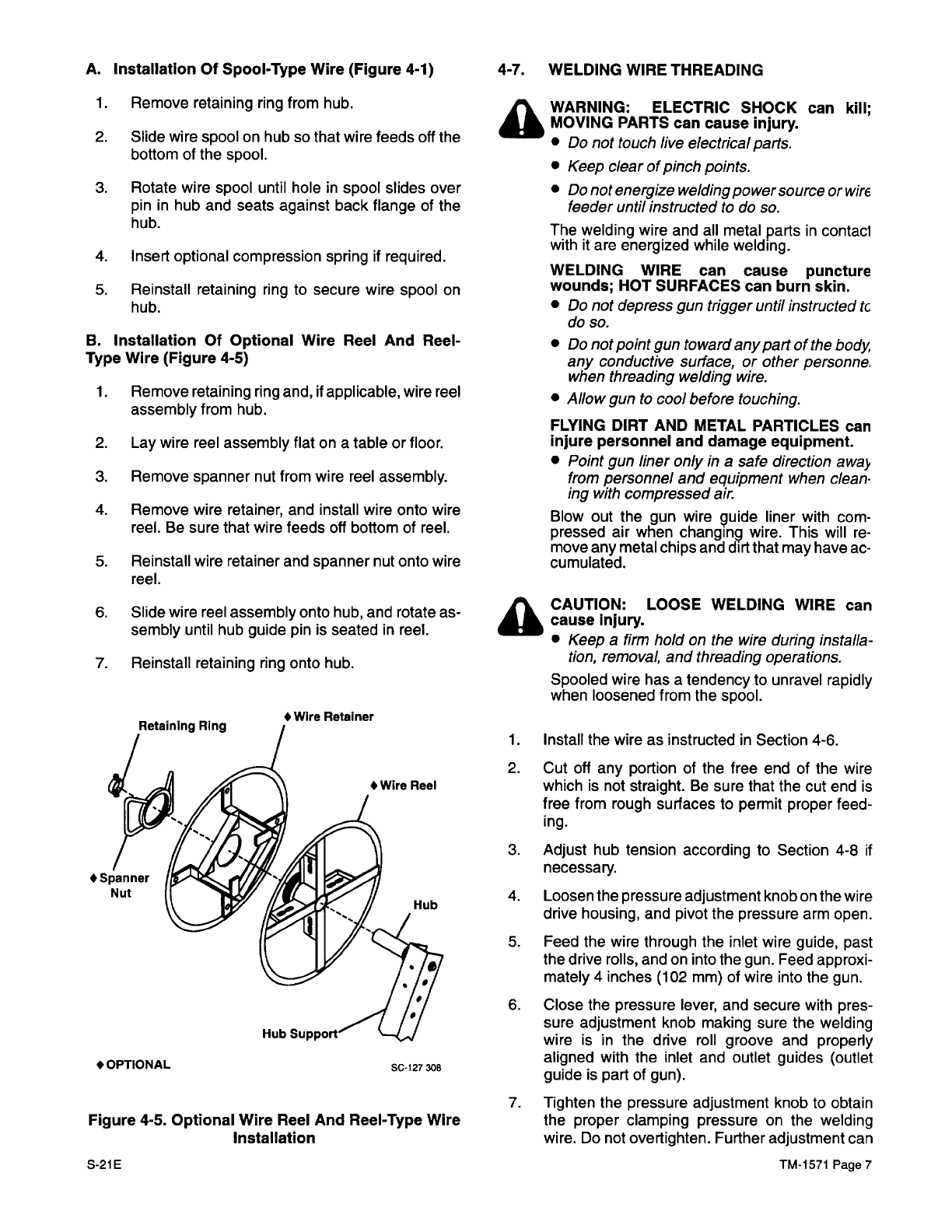
B.
Installation
Of
Optional
Wire
Reel
And
Reel-
Type
Wire
(Figure 4-5)
1.
Remove
retaining
ring
and,
if
applicable,
wire
reel
assembly
from hub.
2.
Lay
wire
reel
assembly
flat
on a
table
or
floor.
3.
Remove
spanner
nut
from
wire
reel
assembly.
4.
Remove wire
retainer,
and
install
wire onto wire
reel.
Be
sure
that
wire
feeds
off
bottom
of
reel.
5.
Reinstall
wire
retainer and
spanner
nut
onto wire
reel.
6.
Slide
wire
reel
assembly
onto
hub,
and
rotate
as
-
sembly
until
hub
guide
pin is
seated in
reel.
7.
Reinstall retaining
ring
onto
hub.
•
Spanner
Nut
•
OPTIONAL
Figure
4-5.
Optional Wire
Reel
And
Reel-Type
Wire
Installation
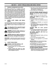
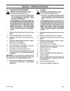
A
A
WARNING:
ELECTRIC
SHOCK
can
kill;
MOVING
PARTS
can
cause
injury.
•
Do
not
touch
live
electrical
parts.
•
Keep
clear
of
pinch
points.
•
Do
not
energize welding
power
source
or
wirE
feeder
until
instructed
to
do
so.
The welding
wire
and
all
metal
parts
in
contaci
with
it
are
energized
while
welding.
WELDING
WIRE can
cause puncture
Wounds;
HOT
SURFACES
can
burn skin.
•
Do
not
depress
gun
trigger
untll
instructed
tc
do
so.
•
Do
not
point
gun towa
rd
any
part of
the
body
any
conductive
surface,
or
other
personne.
when threading
welding
wire.
•
Allow
gun
to
cool before
touching.
FLYING
DIRT
AND
METAL PARTICLES can
injure personnel
and
damage equipment.
•
Point
gun
liner only
in
a
safe direction
awaj~
from
personnel
and
equipment when
clean~
ing with
compressed
air.
Blow
out the
gun
wire
9uide
liner
with
com
-
pressed
air
when
changing
wire.
This
will
re
-
move
any
metal
chips
and
dirt
that
may
have
ac
-
cumulated.
CAUTION:
LOOSE
WELDING
WIRE
can
cause
Injury.
•
Keep
a
firm
hold
on
the wire
during
installa
-
tion,
removal,
and
threading
operations.
Spooled wire
has
a
tendency
to
unravel
rapidly
when
loosened
from
the
spool.
1.Install
the
wire
as
instructed
in
Section 4-6.
2.
Cut
off
any
portion
of
the
free
end
of
the
wire
which
is
not straight.
Be
sure
that
the
cut
end
is
free
from
rough
surfaces
to
permit
proper
feed
-
ing.
3.
Adjust
hub
tension according to Section
4-8
if
necessary.
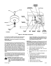
4.
Loosen
the
pressure
adjustment knob
on
the
wire
drive
housing,
and
pivot
the
pressure
arm open.
5.
Feed
the
wire
through
the
inlet
wire
guide, past
the
drive
rolls,
and
on
into
the
gun.
Feed
approxi
-
mately
4
inches
(102
mm)
of
wire
into
the
gun.
6.
Close
the
pressure
lever,
and
secure
with
pres
-
sure
adjustment knob
making
sure
the
welding
wire
is
in
the
drive
roll
groove
and
properly
aligned with
the
inlet
and
outlet
guides
(outlet
guide
is
part of
gun).
7.
Tighten
the
pressure
adjustment knob
to
obtain
the
proper
clamping
pressure
on
the
welding
wire.
Do
not
overtighten. Further
adjustment
can
•Wlre
Retainer
SC-127
306
S-21E
TM-1571
Page
7