


Section
No.
Page
No.
SECTION
8-
TROUBLESHOOTING
8-1.
Testing
Instruments And Information
8-2.
Circuit
Board
Handling
Precautions
8-3.
Troubleshooting
Diagram
8-1.
Troubleshooting
Circuit
Diagram For
Wire Feeder
8-4. Motor
Board
PCi
Testing
Information
Diagram
8-2.
Troubleshooting
Circuit
Diagram For
Motor Control
Board
PCi
8-5.
Optional
SpotlBurnback
Board PC2 Testing
Information
Diagram
8-3.
Troubleshooting
Circuit
Diagram For
Optional Spot/Burnback
Board PC2
SECTION
9-
COMPONENT
IDENTIFICATION
AND
LOCATION
Figure
9-1.
Component
Identification And
Location
SECTION
10—
MAINTENANCE
10-1.
Routine
Maintenance
10-2.
Aligning
Drive
Roll And
Wire
Guide
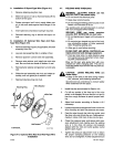
10-3.
Reinstallation
Of
Hub
Assembly
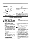
10-4.
Brush
Inspection
And
Replacement
10-5.
Overload
Protection
SECTION
11
-
ELECTRICAL
DIAGRAMS
Diagram
11-1.
Diagram
11-2.
Diagram
11-3.
Diagram
11-4.
Diagram
11-5.
Circuit
Diagram For
S-21
E
Effective
With Serial
No.
JJ507797
And Following
Wiring
Diagram
For
S-21
E
Effective
With
Serial
No.
JJ507797
And Following
Circuit
Diagram For
Motor Control
Board
PCi
Effective
With Serial
No.
JJ507797 And Following
Circuit
Diagram
For
Optional
SpotlBurnback
Board PC2
Effective
With Serial
No.
JJ507797
Thru
JK742028
Circuit
Diagram For
Optional Spot/Burnback
Board PC2
Effective
With Serial
No.
JK742029
And Following
29
29
30
31
32
SECTION
12—
PARTS
LIST
LIST
OF
CHARTS AND
TABLES
Table 3-1.
Specifications
Table 8-1.
Troubleshooting
Table
10-1.
Maintenance
Schedule
Table
11-1.
List
Of
Circuit Diagrams
And
Wiring
Diagrams
3
15
25
28
14
14
14
16
17
18
20
22
24
25
26
26
27
27