


•
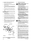
OPTIONAL
Pressure
Roll
Assembly
(Shown
In
Open
PosItion)
It
is
necessary
to
install
the
required
drive
rolls
when
set
-
ting
up
this unit
and
also
when
changing
wire
sizes.
IMPORTANT:
Base drive
roll
selection
on
the
following
recommendations:
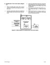
The
dual-grooved drive
roll
provided
with
the
feeder
ac
-
commodates
.023
through
.045
in.
(0.6 through
1.1
mm)
wire.
This
drive
roll
has
both
a
“‘I”
groove
and
a
“‘I”
knurled
groove.
Use
the “V”
groove
for
feeding
.023
and
.030
in.
(0.6 and
0.76
mm)
wire.
Use
the
“V”
knurled
groove
for
feeding
.035
and
.045
in.
(0.89
and
1.1
mm)
wire.
The
wire
size
for
each
groove
is
stamped
on
the
side
of
the
drive
roll.
When
the
drive
roll is
installed
in
the
feeder,
the
wire
size
stamp
for
the
unused
groove
will
be
visible.
The
50
Series wire feeder
style
drive
rolls
may
be
used
with
this feeder,
but,
due to
the flat
idler pressure
roll
used,
a
knurled
drive
roll is
recommended
when
feeding
.035
and
.045
(.089
and
1.1
mm)
wire.
A
W
ARNING:
ELECTRIC
SHOCK
can
kill.
Do
not
store metallic
objects
in
this
compart
-
ment. The
motor
drive
assembly
is
electri
-
cally
hot
whenever
the
welding
circuit
is
ener
-
gized.
Loose
metal
objects
in this
compartment
may
create
an
electrical
path
between
the
weld
out
-
put
circuit and
any
metal
surfaces
or
compo-
nents
resulting in
electric
shock.
IMPORTANT:
Both
types
of
50
Series
style
drive
rolls
can
be reversed
for
reuse
when
they
become
worn.
Re
-
verse
rolls
to
position
unused
groove(s)
to
feed
wire.
The
dual-grooved
drive
roll
pro
vided
with
this
feedercan
be
reversed,
but
only
to
feed a
different
size
wire.
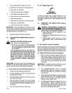
1.
Unlatch
and
open
left
case
access
door.
2.
Loosen
pressure
adjustment
knob,
and
pivot
knob
free of
pressure
arm.
3.
Pivot
pressure
arm
away
to expose
drive
roll
carrier.
4.
For
dual-grooved
roll
supplied
with
feeder:
a.
Choose
the
proper
groove.
b.
Slide
drive
roll onto
drive
roll
mounting hub with
chosen
groove
toward
inside of machine.
The
wire
size
for
the
unused
groove
will
be
visible
after
installation.
c.
Align
the
drive
roll
with
holes.
d.
Insert
securing
screws, and tighten.
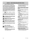
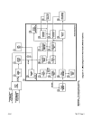
Hub
Wire
•
Spring
9
Retaining
Ring
Ret.
50497
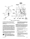
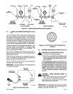
Figure
4-1.
Wire
Feeder
Components
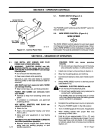
GunlFeeder
connector
Securing
Knob
Ref.
SB-125
923
TM-1571
Page
4
5-21E