


SECTION
5-
OPERATOR
CONTROLS
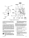
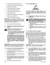
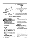
5-1.
POWER
SWITCH
(Figure 5-1)
POWER
The
POWER switch
functions as
the
ON/OFF switch
for
the
wire
feeder.
5-2. WIRE SPEED
CONTROL
(Figure 5-1)
WIRE SPEED
ojo
The
WIRE
SPEED
control
adjusts
the
wire
feed
speed
88-124
467
in
inches per
minute
within
the
wire
speed
range.
Rotat
-
ing
the WIRE
SPEED
control
clockwise
increases
wire
feed
speed.
The
scale
is
calibrated
in
inches per
minute.
SECTION
6—
SEQUENCE
OF
OPERATION
6-1.
GAS
METAL
ARC
(GMAW)
AND
FLUX
CORED
ARC
(FCAW)
WELDING
A
WARNING: ELECTRIC
SHOCK
can kill;
MOVING
PARTS
can
cause
serious
injury;
EXPOSURE
TO
ENVIRONMENT
can
damage
internal parts.
•
Do
not
touch
live
electrical
parts.
•
Keep
case
closed
while operating.
Warranty
is
void
if
the
wire
feeder
is
operated
with
any
portion
of
the
outer
enclosure open
or
removed.
ARC
RAYS
can
burn
eyes
and
skin; NOISE
can
damage hearing.
•
Wear
correct
eye,
ear,
and body
protection.
FUMES
AND
GASES can
seriously
harm
your
health.
•
Ventilate
to
keep
from
breathing
fumes
and
gases.
•
If
ventilation
is
inadequate,
use
approved
breathing
device.
HOT
METAL,
SPATrER,
AND
SLAG
can
cause
fire
and
burns.
•
Watch
for
fire.
•
Keep
a
fire
extinguisher
nearby
and
know
how
to
use
it.
•
Allow
work
and
equipment
to
cool
before
handling.
MAGNETIC
FIELDS
FROM
HIGH
CURRENTS
can
affect
pacemaker operation.
•
Wearers
should
consult
their
doctor
before
going
near
arc
welding
gouging,
or
spot
5-21
E
welding
operations.
WELDING
WIRE can
cause
puncture
Wounds.
•
Do
not
point
gun
toward
any
part of
the
body
any
conductive
surface,
or
other
personnel.
1.
Install
and
connect
unit
according
to Section
4.
2.
Wear
dry
insulating gloves
and
clothing.
3.
Connect
work
clamp
to
clean,
bare metal
at
work-
piece.
4.
Rotate
WIRE
SPEED
control
to
desired
position
(see
Section
5-2).
A
WARNING:
ELECTRIC
SHOCK
can kill.
•
Do
not
touch
live
electrical
parts.
•
Do
not
touch welding
wire
or
any
metal
part
in
contact
with
it
while
welding.
The
welding
wire
and all
metal
parts
in
contact
with
it
carry
weld
output when
the
welding
power
source
contactor
is
energized.
5.
Energize
the
welding
power
source
or
generator.
6.
Place
the
POWER switch
in
the
ON
position
7.
Turn
on
shielding
gas
at
the
source,
if
applicable.
8.
Wear
welding
helmet with
proper filter lens
according
to
ANSI Z49.1.
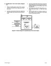
9.
Hold
tip
of gun
approximately
1/2 in.
(13
mm)
from
workpiece,
and
depress
gun
trigger.
Current
flows,
gas
flows,
and
wire
feeds.
If
wire
slippage
is
noticed,
adjust drive
roll
pressure
according
to
Section 4-7.
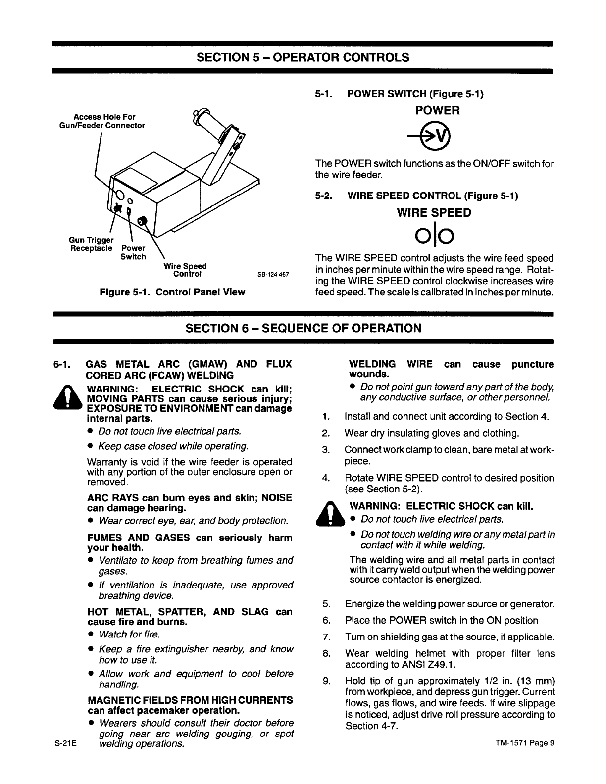
Access
Hole
For
Gun/Feeder
Connector
Gun
Trigger
Receptacle
Wire
Speed
Control
Figure
5-1.
Control
Panel
View
TM-1571
Page
9