


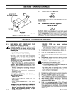

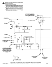
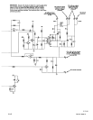
8-4.
MOTOR BOARD
PCi
TESTING
INFORMA
-
TION
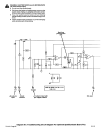
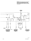
(Figure
8-1
And
Diagram 8-2)
A
W
ARNING:
ELECTRIC
SHOCK
can
kill.
Do
not
touch
live
electrical
parts.
•
Shut
down
wire
feeder and
welding
power
source
or
stop
engine
before
making
or
changing
meter
lea
d
connections
and
before
disconnecting
or
connecting
any
leads.
MOVING
PARTS
can
cause
serious
injury.
•
Keep
away
from
moving
parts.
HOT
SURFACES
can
cause
severe burns.
•
Allow
cooling
period
before servicing.
This
procedure requires the
unit
to
be
ener
-
~
ized.
Only
qualified
persons
familiar
with
and
ollowing
standard
safety practices
are
to
per-
form this
testing
procedure.
A
CAUTION:
ELECTROSTATIC
DISCHARGE
(ESD)
can
damage
circuit
boards.
•
Put
on
properly
grounded
wrist
strap
BE-
FORE
handling
circuit
boards.
•
Transport
circuit
boards
in
proper
static-
shielding
carriers
or
packages.
•
Perform
work
only
at
a static-safe
work
area.
INCORRECT
INSTALLATION
or
misaligned
plugs
can
damage
circuit board.
•
Be
sure
that
plugs
are
properly
installed
and
aligned.
EXCESSIVE
PRESSURE
can
break
circuit
board.
•
Use
only
minimal pressure and
gentle
move
-
ment
when
disconnecting
or
connecting
board
plugs
and
removing
orin
stalling
board.
IMPORTANT:
For all checks,
be
sure
to
test
and
verify
the
continuity
of
leads between
the
board
and
the
area
where
check
is
performed.
All
checks
should
go
through
the
connections
and be
actual
terminal-to-terminal
tests
so
that
bad
connections
or
leads
and
corrosion
are
not
the
problem.
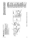
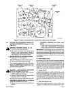
A.
Preliminary
Checks
1.
Check
that
jumper
plug
PLGl
is
secure
in
recep
-
tacle
RC1
on
Motor
Control
Board
PCl.
2.
Check
that
plug
PLG2
is
secure
in
receptacle
RC2
on
Motor
Control
Board
PCl.
3.
Check
that
plug
PLG3
is
secure
in
receptacle
RC3
on
Motor
Control
Board
PCl.
4.
Check
that
plug
PLG4
is
secure
in
receptacle
RC3
on
Motor
Control
Board
PCi.
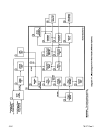
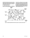
B.
Power
Supply
Circuit
Input power
of
24
volts ac
should
be
present
between
pins
A
and
B
of
receptacle
RC4.
If
24
volts ac
are
not
present,
check
POWER
switch
51
and
circuit
breaker
CBl
for
proper operation
with
an
ohmmeter.
An
output
voltage
of +24
volts dc
should
be
present at
pin A
of receptacle
RC2
with
respect
to
circuit
common.
If
+24
volts dc
are
not
present
at
pin
A,
replace
Motor
Control
Board
PCl.
An
output voltage
of
+6.5 volts dc
should
be
present
at
pin C
of
receptacle
RC2
with
respect
to
circuit
common
with
gun
trigger
pressed.
If +6.5 volts dc
are
not
present
at
pin C,
replace
Motor
Control
Board
PCi.
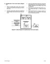
C.
Trigger
Circuit
When
the
gun
trigger
is
pressed, +19
volts dc
should
be
present
at
pin B
of
receptacle
RC2
with
respect
to
circuit
common
otherwise
the
voltage
at
pin
B
should
be
0 volts
dc
when
the
gun
trigger
is
not
pressed.
The
trigger
signal
is
then
supplied
to
pin A
of
receptacle
RCl
as a motor
start/stop
control signal
and
also supplied
to
pin
B
of
re
-
ceptacle
RCl
to
control
gas
valve
GS1
and
contactor
control relay
CR1
on
PCi.
D.
Wire
Feed Speed
Circuit
The
0
to
+6.5 volts dc
wire
feed
speed
command
input
signal
should
be
present
at
pin D
of
receptacle
RC2.
The
wire
feed
speed
command
signal
is
compared
to
the
current
and
voltage
feedback
from
Motor
Ml
thereby
providing the
proper
voltage
output
of
0
to +24
volts dc
to
wire
drive
motor
Ml
through
pins
D
(positive)
and C
(negative)
of
receptacle
RC4.
If
0
to +24
volts dc
is
not
present
between pins
C
and
D
of
RC4,
replace
Motor
Control
Board
PCi.
5-2iE TM-i57i
Page
17