


ceptacle
RC2
with
respect
to
circuit
common to
start
the
motor
and
0 volts dc should
be
present
when
the
gun
trigger
is
released to
stop
the
motor.
If
+24
volts dc
are
not
present
at
pin A
when
the
gun
trigger
is
pressed,
re
-
place
Spot/Burnback
Board
PC2.
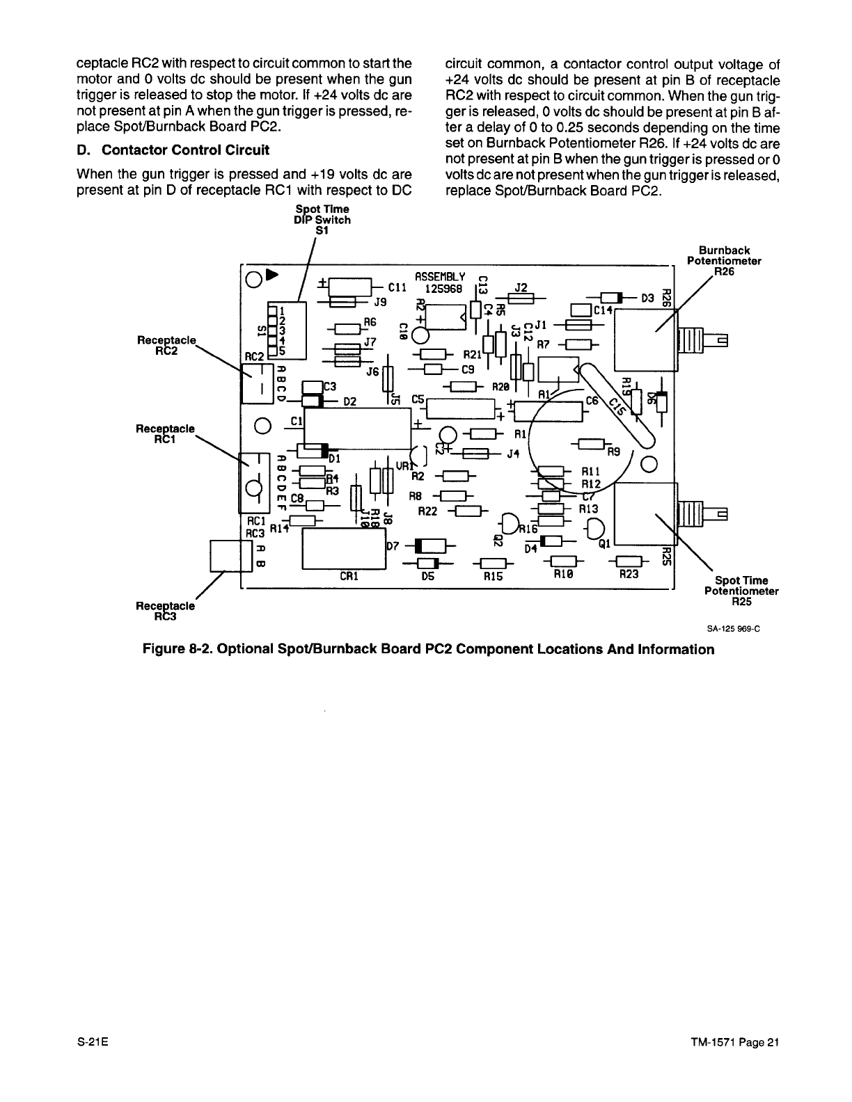
D.
Contactor
Control
Circuit
When the
gun
trigger
is
pressed
and +19
volts dc
are
present at
pin D
of
receptacle
RCl
with
respect
to
DC
Spot
Time
DIP
Switch
Si
circuit
common,
a
contactor
control
output voltage
of
+24
volts dc
should
be
present
at
pin B
of
receptacle
RC2
with
respect
to
circuit
common.
When the
gun
trig
-
ger
is
released,
0 volts dc should
be
present at
pin
B
af
-
ter
a
delay
of
0
to
0.25
seconds depending
on
the
time
set
on
Burnback Potentiometer
R26.
If
+24
volts
dc
are
not
present
at
pin B
when
the
gun
trigger
is
pressed
or
0
volts dc
are
not
present
when
the
gun
trigger
is
released,
replace
Spot/Burnback
Board
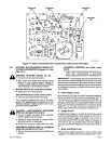
P02.
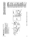
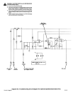
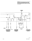
SA-125
969-C
Figure
8-2.
Optional SpotlBurnback
Board
PC2
Component Locations
And
Information
S-2iE
TM-1571
Page
21