


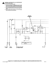
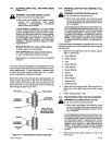

10-2.
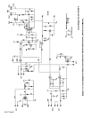
ALIGNING
DRIVE
ROLL
AND
WIRE
GUIDE
(Figure
10-1)
A
W
ARNING:
ELECTRIC
SHOCK
can
kill.
Do
not
touch
live
electrical
parts.
•
Shut
down wire
feeder and
welding
power
source,
and
disconnect
input
power
employing
lockout/tagging
procedures
be
ore
working
on
feeder.
Lockout/tag
9ing procedures
for wire
feeder
consist
of
disconnecting
interconnecting
cord,
and
for
welding
power
source consist
of
pad
-
lockin9
line
disconnect switch
in
open
position,
removing
fuses
from
fuse
box,
or
shutting
off
and
red-tag9ing
circuit
breaker
or
other
discon
-
necting device.
Stop
engine,
and
disconnect
negative
(—)
battery
cable
from battery
on
weld-
ing
generators.
MOVING
PARTS
can
cause
serious
injury.
•
Keep
away
from
moving
parts.
HOT
SURFACES
can
cause
severe
burns.
•
Allow
cooling
period
before servicing.
Maintenance
to
be
performed
only
by
qualified
persons.
The
drive
roll and
wire
guide
must
be
aligned
for wire
to
feed
properly.
Alignment
is
factory set
and
should
not
re
-
quire
readjustment.
To
check
alignment,
compare
drive
roll and
wire
guide positions
with
Figure
10-1.
If
align
-
ment
is
necessary,
proceed
as follows:
Behind
the drive
roll
mounting
hub
is
a
spring washer.
To
obtain
proper
alignment
of
the drive
roll
with
the
wire
guide,
rotate
drive
roll
mounting
hub
securing bolt,
and
move
drive
roll
in
or
out
until
groove
in
drive
roll
lines
up
with
wire
guide
(see
Figure
10-1).
Wire
Guide_-
CORRECT
A
ALIGNMENT
Drive
Roll
Washer
INCORRECT
ALIGNMENT
Secrurlng
Bolt
Welding Wire
V
Drive
Roll
Mounting
Hub
View
Is
from
top
of
feeder
looking
down
with
pressure
roll
assembly
open
I
SA
145763
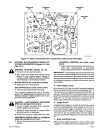
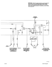
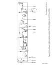
10-3.
REINSTALLATION
OF HUB
ASSEMBLY
(Fig
-
ure
10-2)
A
WARNING: ELECTRIC
SHOCK
can
kill.
•
Do
not
touch
live
electrical
parts.
•
Shut
down
wire
feeder and
welding
power
source,
and
disconnect
input
power
employ
-
ing
lockout/tagging
procedures
before
work
-
ing
on
feeder.
Lockout/tagging procedures
for wire
feeder
con-
sist
of
disconnecting
interconnecting
cord,
and
for
welding
power
source consist
of
padlocking
line
disconnect
switch
in
open
position,
remov
-
ing
fuses
from
fuse box,
or
shutting
off
and
red
-
tagging
circuit
breaker
or
other
disconnecting
device.
Stop
engine,
and
disconnect negative
(—)
battery
cable
from
battery
on
welding
gen
-
erators.
If
it
should
become necessary
to
replace
any
part
of
the
assembly,
obtain
part and
proceed
as follows
to reinstall
the
assembly.
1.
Slide the
following
items
onto
the
spool
support
shaft
in
order
given:
a.
Fiber
Washer
b.
Brake
Washer
c.
Hub
d.
Brake
Washer
e.
Fiber
Washer
f.
Keyed
Washer
g.
Spring
h.
Wire
Reel
i.
Wire
Retainer
j.
Spanner
Nut
k.
Retaining
Ring
2.
Rotate
bolt into
support
shaft.
Bolt should
be
ro
-
tated
only
until
a
slight
drag
is
felt while
turning
hub.
3.
Install
retaining
ring
on
hub.
10-4.
BRUSH
INSPECTION
AND
REPLACEMENT
A
WARNING: ELECTRIC
SHOCK
can
kill.
•
Do
not
touch
live
electrical
parts.
•
Shut
down wire
feeder
and
welding
power
source,
and
disconnect
input
power
employ
-
ing
lockout/tagging
procedures
before
work
-
ing
on
feeder.
Lockout/tagging procedures
forwire
feedercon
-
sist
of
disconnecting
interconnecting
cord,
and
for
welding
power
source
consist
of
padlocking
line
disconnect
switch
in
open
position,
remov
-
ing
fuses
from
fuse
box,
or
shutting
off
and
red-
tagging
circuit
breaker
or
other
disconnecting
device.
Stop
engine,
and
disconnect negative
(—)
battery
cable
from
battery
on
welding
gen
-
erators.
Figure
10-1.
Reinstallation
Of
Hub
Assembly
TM-1571 Page
26
1.
Remove
two
brush caps
located
on
end of
the
drive
motor.
S-21E