


OM-169 510 Page 6
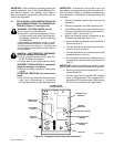
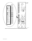
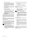
LEFT SIDE RIGHT SIDE
Robot Control
S-0782
Blank Cover Plates
Blank Cover Plates
(Both Rows)
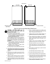
Figure 3-6. View Of Left And Right Sides Of Robot Control
WARNING: ELECTRIC SHOCK can kill.
ELECTROSTATIC DISCHARGE (ESD) can
damage circuit boards.
•
Do not touch live electrical parts.
•
Shut down welding power source and Robot
Control, and disconnect input power employ-
ing lockout/tagging procedures before in-
specting high-frequency filter.
Lockout/tagging procedures consist of padlock-
ing line disconnect switch in open position, re-
moving fuses from fuse box, or shutting off and
red-tagging circuit breaker or other disconnect-
ing device.
•
Put on properly grounded wrist strap BE-
FORE handling circuit boards or making con-
nections inside Robot Control.
•
Transport circuit boards in proper static-
shielding carriers or packages.
•
Perform work only at a static-safe work area.
a. Open Robot Control cabinet door using the two
supplied keys, and rotate the power switch han-
dle beyond the OFF position to the Reset/Open
position.
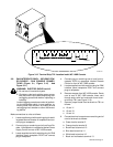
b. Select and remove a blank cover plate from Ro-
bot Control for installing high-frequency filter
(see Figure 3-6).
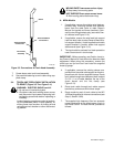
c. Remove screws securing cover to high-fre-
quency filter box, and remove cover from box.
d. Insert cord attached to box through opening in
Robot Control side panel where cover plate was
removed.
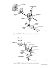
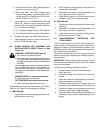
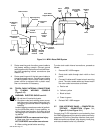
e. Place a supplied external star washer over
each screw, and thread screws into mounting
holes in side panel (see Figure 3-7).
f. Tighten screws until star washers flatten and
penetrate through paint into metal surface.
g. Place remaining star washers over threaded
portion of each screw extending out from side
panel inside Robot Control, and install nut on
each screw.
h. Tighten nuts until star washers flatten and
penetrate through paint into metal surface.
i. Reinstall and secure cover onto filter box.
j. Route high-frequency cord inside Robot Con-
trol to Interlock board on left side panel of cabi-
net.
k. Route black and white leads to terminal block
TB1 (see Figure 3-9).
l. Connect black lead to terminal 4 on TB1.
m. Connect white lead to terminal 5 on TB1.
n. Close and secure Robot Control cabinet door.
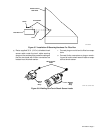
o. Disconnect friction terminals on leads of exist-
ing shock sensor cord from shock sensor leads
at welding gun body (see Figure 3-8).
p. Remove existing shock sensor cord by discon-
necting plug from receptacle on robot.