


OM-169 510 Page 13
SECTION 4 – ROBOT PROGRAM MODIFICATIONS
IMPORTANT:
The robot program must be changed to
accommodate plasma arc welding. The program is fac-
tory set to accommodate factory installed plasma arc
welding equipment. The following information pertains
to the robot Owner’s Manual and must be followed when
field installing plasma arc welding equipment.
WARNING: ELECTRIC SHOCK can kill.
•
Do not touch live electrical parts.
•
Shut down robot and welding power source,
and disconnect input power employing lock-
out/tagging procedures before inspecting or
installing.
Lockout/tagging procedures consist of pad-
locking line disconnect switch in open position,
removing fuses from fuse box, or shutting off
and red-tagging circuit breaker or other discon-
necting device.
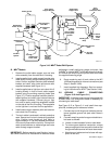
4-1. SETTING UP PLASMA (NON-STANDARD)
TORCH FOR MRH
2
ROBOT (Figure 4-1)
It is necessary to use the robot Owner’s Manual in addi-
tion to this manual to complete the proper installation of
the torch.
IMPORTANT:
Follow entire procedure in presented or-
der.
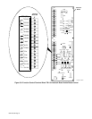
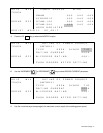
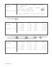
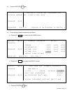
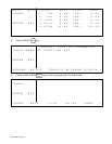
1. Check System Data settings against the test
sheet supplied with the unit. These should match
before beginning installation.
2. Mount plasma arc welding torch according to
Section 3-3 of this manual. Make sure that sup-
plied brass tip gauge and holder have been
installed on torch.
3. Do tool center point adjustment according to Sec-
tion 4.6 of the robot Owner’s Manual.
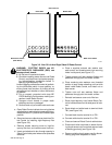
4. The universal J-bar is included to record exact
torch position so that it is possible to recover posi-
tion in case of a robot crash. Install universal J-
bar as follows:
a. Remove 2 screws and cover plate from bottom
of Axis 5 gear housing.
b. Install universal J-bar onto Axis 5 by aligning in-
dex pin with hole in housing, and securing with
supplied screws.
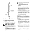
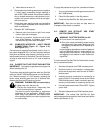
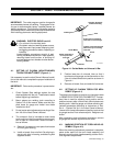
Indexing Pin
Scribe Marks
Scribe marks where
torch tip touches
lower bar.
Lower Bar
Setscrew
Screw
Attaches To Bottom
Of Axis 5 Housing
Rod
Scribe around rod below
lower bar to record height.
Tighten screw and setscrew
when torch tip is touching
lower bar.
ST-146 220
Figure 4-1. Scribe Marks on Universal J-Bar
5. Position lower bar of universal J-bar so that it
touches torch tip gauge, and scribe marks on the
J-bar to indicate exact torch position as shown in
Figure 4-1.
6. Remove universal J-bar, and retain for future use.
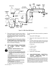
4-2. SETTING UP PLASMA TORCH FOR MRV
2
ROBOT (Figure 4-1)
The plasma torch does not require any changes to data
in PARMTER/SYSTEM/TOOL PARAMETER. The stan-
dard I-bar is used for adjusting torch position and for
position recovery after a robot crash. Mount plasma arc
welding torch, install tip gauge, and follow mounting ad-
justment procedures according to instructions in Sec-
tion 4 – System Set Up in the robot Owner’s Manual.
Loosen torch clamp setscrews and position torch so that
tip gauge touches I-bar reference point. Retighten set-
screw.
After completing torch adjustment procedure, remove
tip gauge and reinstall cup onto end of torch.
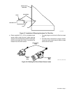
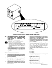
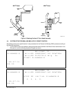
4-3. MARKING POSITION OF TORCH HEAD AS-
SEMBLY (Figure 4-2)
When the mounting adjustment procedure is complete,
place scribe marks on the torch head assembly and
sleeve to mark the torch head assembly position for fu-
ture alignment adjustments.