


OM-169 510 Page 5
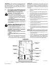
ST-800 836
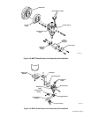
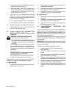
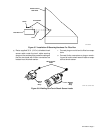
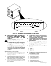
Sleeve
Green And Black
Connections
Yellow And Red
Connections
Torch Head
Assembly
Figure 3-5. Connections At Torch Head Assembly
7. Screw sleeve onto torch head assembly.
8. Secure shield sleeving to torch cable using sup-
plied clamp.
3-4. TORCH AND TORCH CABLE INSTALLATION
TO ROBOT (Figure 3-3 Thru Figure 3-11)
WARNING: ELECTRIC SHOCK can kill.
•
Do not touch live electrical parts.
•
Shut down robot and welding power source,
and disconnect input power employing lock-
out/tagging procedures before inspecting or
installing.
Lockout/tagging procedures consist of padlock-
ing line disconnect switch in open position, re-
moving fuses from fuse box, or shutting off and
red-tagging circuit breaker or other disconnect-
ing device.
MOVING PARTS can cause serious injury.
•
Keep away from moving parts.
HOT SURFACES can cause severe burns.
•
Allow cooling period before servicing.
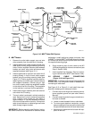
A. MRH
2
Models
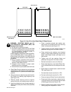
1. If applicable, remove the existing wire feed mo-
tor/reed relay mounting bracket and stabilizer
brace from the robot (refer to robot Owner’s
Manual for bracket and brace locations). Rein-
stall the two lifting brackets only (see robot Own-
er’s Manual and Figure 3-10).
2. If applicable, remove the wire feed hub support
from the robot (refer to robot Owner’s Manual for
hub support location). Install supplied torch cable
support bracket in location where hub support
was secured (see Figure 3-10).
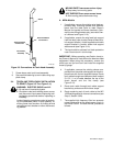
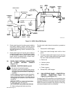
3. The torch cable is enclosed in a black protective
case. Secure torch in torch clamp.
IMPORTANT:
Before operating, see Section 4 and ro-
bot Owner’s Manual for instructions for absolute offset
adjustment. When doing this procedure, remove the
shield cup and tip from torch and install the supplied
brass tip gauge.
4. If applicable, remove the existing clamps sus-
pended from the outlet cable support arm and re-
place them with the two supplied clamps. Route
torch cable through new clamps so there is about
3-1/2 ft. (1 m) of cable between the top of the
shock sensor and the first clamp (see
Figure 3-10).
5. Route torch cable through torch cable support
bracket tray and secure with rubber straps.
6. Route remaining end of torch cable to the WC
100B welding panel for internal connections (see
Step 3, Section 3-6B).
7. The supplied high frequency filter box prevents
noise interference at the shock sensor circuit in
the Robot Control. To install the filter, proceed as
follows: