


OM-169 510 – 6/95
EMF INFORMATION
The following is a quotation from the General Conclusions Section
of the U.S. Congress, Office of Technology Assessment,
Biological
Effects of Power Frequency Electric & Magnetic Fields –
Background Paper
, OTA-BP-E-53 (Washington, DC: U.S.
Government Printing Office, May 1989): “. . . there is now a very
large volume of scientific findings based on experiments at the
cellular level and from studies with animals and people which clearly
establish that low frequency magnetic fields can interact with, and
produce changes in, biological systems. While most of this work is
of very high quality, the results are complex. Current scientific
understanding does not yet allow us to interpret the evidence in a
single coherent framework. Even more frustrating, it does not yet
allow us to draw definite conclusions about questions of possible
risk or to offer clear science-based advice on strategies to minimize
or avoid potential risks.”
To reduce magnetic fields in the workplace, use the following
procedures:
1. Keep cables close together by twisting or taping them.
2. Arrange cables to one side and away from the operator.
3. Do not coil or drape cables around the body.
4. Keep welding power source and cables as far away as
practical.
5. Connect work clamp to workpiece as close to the weld as
possible.
About Pacemakers:
The above procedures are among those also normally
recommended for pacemaker wearers. Consult your doctor for
complete information.
Considerations About Welding And The Effects Of Low Frequency Electric And
Magnetic Fields
NOTE
mod10.1 4/93
TABLE OF CONTENTS
SECTION 1 – SAFETY PRECAUTIONS AND SIGNAL WORDS 1. . . . . . . . . . . . . . . . . . . . . . . . . . . . . . .
1-1. General Information And Safety 1. . . . . . . . . . . . . . . . . . . . . . . . . . . . . . . . . . . . . . . . . . . . . . . . . .
1-2. Safety Alert Symbol And Signal Words 1. . . . . . . . . . . . . . . . . . . . . . . . . . . . . . . . . . . . . . . . . . . .
SECTION 2 – INTRODUCTION 1. . . . . . . . . . . . . . . . . . . . . . . . . . . . . . . . . . . . . . . . . . . . . . . . . . . . . . . . . . . .
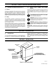
2-1. Description 1. . . . . . . . . . . . . . . . . . . . . . . . . . . . . . . . . . . . . . . . . . . . . . . . . . . . . . . . . . . . . . . . . . . .
SECTION 3 – INSTALLATION 1. . . . . . . . . . . . . . . . . . . . . . . . . . . . . . . . . . . . . . . . . . . . . . . . . . . . . . . . . . . . .
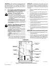
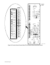
3-1. Field Installation Instructions For PAW Interface Panel To Computer Interface 2. . . . . . . . . .
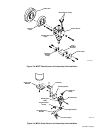
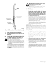
3-2. Shock Sensor Unit Assembly And Installation To Robot 4. . . . . . . . . . . . . . . . . . . . . . . . . . . . . .
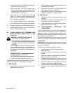
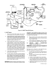
3-3. High-Frequency Protection For Torch Cable 4. . . . . . . . . . . . . . . . . . . . . . . . . . . . . . . . . . . . . . . .
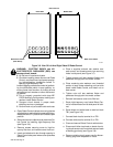
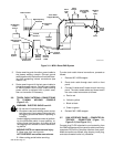
3-4. Torch And Torch Cable Installation To Robot 5. . . . . . . . . . . . . . . . . . . . . . . . . . . . . . . . . . . . . . .
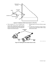
3-5. Ground Cable Connections 9. . . . . . . . . . . . . . . . . . . . . . . . . . . . . . . . . . . . . . . . . . . . . . . . . . . . . .
3-6. Torch Cable Internal Connections To Plasma Welding Console 10. . . . . . . . . . . . . . . . . . . . . . .
3-7. PAW Interface Panel – Computer Interface Connection 10. . . . . . . . . . . . . . . . . . . . . . . . . . . . . .
3-8. PAW Interface Panel – Welding Power Source – PAW Console Connections 11. . . . . . . . . . .
3-9. Computer Interface – Input Power Connections 12. . . . . . . . . . . . . . . . . . . . . . . . . . . . . . . . . . . . .
3-10. Gas Set/Pilot Arc Start Push Button 12. . . . . . . . . . . . . . . . . . . . . . . . . . . . . . . . . . . . . . . . . . . . . . .
3-11. Remote Gas Set/Pilot Arc Start Switch Connections 12. . . . . . . . . . . . . . . . . . . . . . . . . . . . . . . . .
SECTION 4 – ROBOT PROGRAM MODIFICATIONS 13. . . . . . . . . . . . . . . . . . . . . . . . . . . . . . . . . . . . . . . . .
4-1. Setting Up Plasma (Non-Standard) Torch For MRH
2
Robot 13. . . . . . . . . . . . . . . . . . . . . . . . . .
4-2. Setting Up Plasma Torch For MRV
2
Robot 13. . . . . . . . . . . . . . . . . . . . . . . . . . . . . . . . . . . . . . . . .
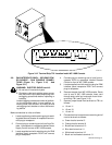
4-3. Marking Position Of Torch Head Assembly 13. . . . . . . . . . . . . . . . . . . . . . . . . . . . . . . . . . . . . . . . .
4-4. System Setup For MRH
2
And MRV
2
With C2 Robot Control 14. . . . . . . . . . . . . . . . . . . . . . . . . .
SECTION 5 – ELECTRICAL DIAGRAMS 21. . . . . . . . . . . . . . . . . . . . . . . . . . . . . . . . . . . . . . . . . . . . . . . . . . .
Figure 5-1. Circuit Diagram For Robot PAW System 21. . . . . . . . . . . . . . . . . . . . . . . . . . . . . . . . . . . . . . .
Figure 5-2. Circuit Diagram For Robot PAW Interface Panel 22. . . . . . . . . . . . . . . . . . . . . . . . . . . . . . . .
Figure 5-3. Wiring Diagram For Robot PAW Interface Panel 22. . . . . . . . . . . . . . . . . . . . . . . . . . . . . . . .
Figure 5-4. Circuit Diagram For High-Frequency Filter 23. . . . . . . . . . . . . . . . . . . . . . . . . . . . . . . . . . . . .
Figure 5-5. Wiring Diagram For High-Frequency Filter 23. . . . . . . . . . . . . . . . . . . . . . . . . . . . . . . . . . . . .
SECTION 6 – HF IN PLASMA ARC WELDING 24. . . . . . . . . . . . . . . . . . . . . . . . . . . . . . . . . . . . . . . . . . . . . .
SECTION 7 – PARTS LIST 26. . . . . . . . . . . . . . . . . . . . . . . . . . . . . . . . . . . . . . . . . . . . . . . . . . . . . . . . . . . . . . . .