


OM-169 510 Page 9
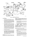
WC 100B
Plasma
Shock Sensor
Cable
Torch Cable
Support Bracket
115VAC Input
Power Cord
Ground
Rod No.2
Outlet Cable
Support Arm
Clamps
Torch
Cable In
Shock
Torch
Braided Ground
Cable
Lifting
Bracket
Ground Cable
Securing Bolt
Location
Welding Gun
Body
Protective Case
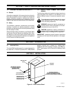
Robot Control
High Frequency
Filter Box
Welding
Console
Sensor
Cable
Coolant
System
PAW/Computer
Interface
DC Welding
Power Source
ST-800 734
Ground
Rod No.1
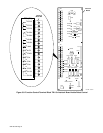
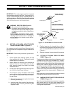
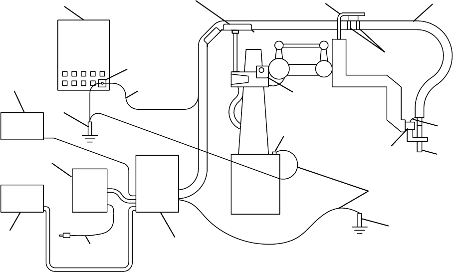
Figure 3-10. MRH
2
Robot PAW System
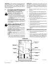
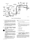
B. MRV
2
Models
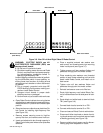
1. Remove the outlet cable support arm and wire
drive assembly from the robot Axis 3 housing.
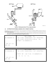
2. Install supplied torch cable support bracket onto
robot Axis 3 housing using the existing mounting
holes. Position supplied insulator plate between
bracket and robot, align holes and secure with
supplied hardware (see Figure 3-11).
3. Install supplied servo light box onto robot Axis 3
housing directly in front of torch cable support
bracket using the existing mounting holes (see
Figure 3-7). Position supplied insulator plate be-
tween light box and robot, align holes and secure
with supplied hardware. Connect plug on light
box cord to nearby matching receptacle located
on the side of the Axis 3 housing. The receptacle
on the light box is not used for this application.
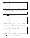
4. Install cable hanger assembly with tool balancer
onto robot Axis 3 housing.
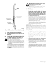
5. The torch cable is enclosed in a black protective
case. Secure torch in torch clamp using supplied
shim. Position torch handle so that there is
approximately 4 in. (96 mm) between the bottom
of the torch clamp and the torch tip. Clamp torch
cable to tool balancer on cable hanger and route
cable through support bracket.
IMPORTANT:
Before operating, see Section 4 and ro-
bot Owner’s Manual for instructions for absolute offset
adjustment. Install positioning gauge (universal J-bar
for MRH
2
or I-bar for MRV
2
) onto robot output hub brack-
et. Remove the shield cup and tip from torch and install
the supplied brass tip gauge.
6. Route remaining end of torch cable to the WC
100B welding panel for internal connections (see
Step 3, Section 3-6B).
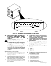
7. Install supplied high frequency filter box accord-
ing to instructions for MRH
2
(see Section 3-4A).
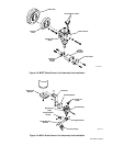
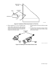
3-5. GROUND CABLE CONNECTIONS
(Figure 3-10 And Figure 3-11)
IMPORTANT:
If welding power source is equipped with
a plastic case, only one ground cable is necessary for
connecting to robot base.
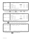
See Figure 3-10 or Figure 3-11 and install three sup-
plied flat, braided ground cables as follows:
1. Connect one end of the ground cables to the cus-
tomer-supplied ground rod (see robot Owner’s
Manual).
2. Connect remaining end of one ground cable to ro-
bot base as follows:
a. Locate unused threaded hole on robot base.
b. To ensure good electrical conduction, scrape
away enough paint from around the hole so that
the ground cable terminal will touch bare metal.
c. Attach ground cable terminal to base with sup-
plied 12 mm bolt.