


OM-169 510 Page 2
IMPORTANT:
When installing or operating plasma arc
welding equipment, refer to the Plasma Welding Con-
sole Owner’s Manual and Welding Torch Owner’s
Manual for specific precautionary information that ap-
plies to this equipment.
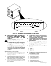
3-1. FIELD INSTALLATION INSTRUCTIONS FOR
PAW INTERFACE PANEL TO COMPUTER IN-
TERFACE (Figure 3-1 And Figure 3-2)
WARNING: ELECTRIC SHOCK can kill.
•
Do not touch live electrical parts.
•
Shut down robot and welding power source,
and disconnect input power employing lock-
out/tagging procedures before beginning
this installation.
Lockout/tagging procedures consist of pad-
locking line disconnect switch in open position,
removing fuses from fuse box, or shutting off
and red-tagging circuit breaker or other discon-
necting device.
CAUTION: ELECTROSTATIC DISCHARGE
(ESD) can damage circuit boards.
•
Put on properly grounded wrist strap BE-
FORE handling circuit boards.
•
Perform work only at a static-safe work area.
INCORRECT INSTALLATION or misaligned
plugs can damage circuit board.
•
Be sure that plugs are properly installed and
aligned.
EXCESSIVE PRESSURE can break circuit
board.
•
Use only minimal pressure and gentle move-
ment when disconnecting or connecting
board plugs and removing or installing board.
IMPORTANT:
All directions, such as left or right, are
with respect to the operator facing the Computer Inter-
face front panel. Retain all hardware removed during
this procedure for reinstallation unless specifically told
otherwise.
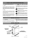
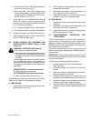
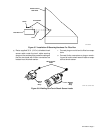
1. Remove Computer Interface top cover and left
side panel.
2. Remove side panel from PAW Interface panel.
3. Install PAW Interface frame onto left side panel of
Computer Interface with sheet metal screws re-
moved in Step 1 (see Figure 3-1).
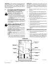
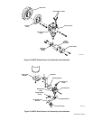
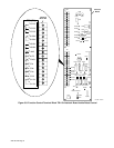
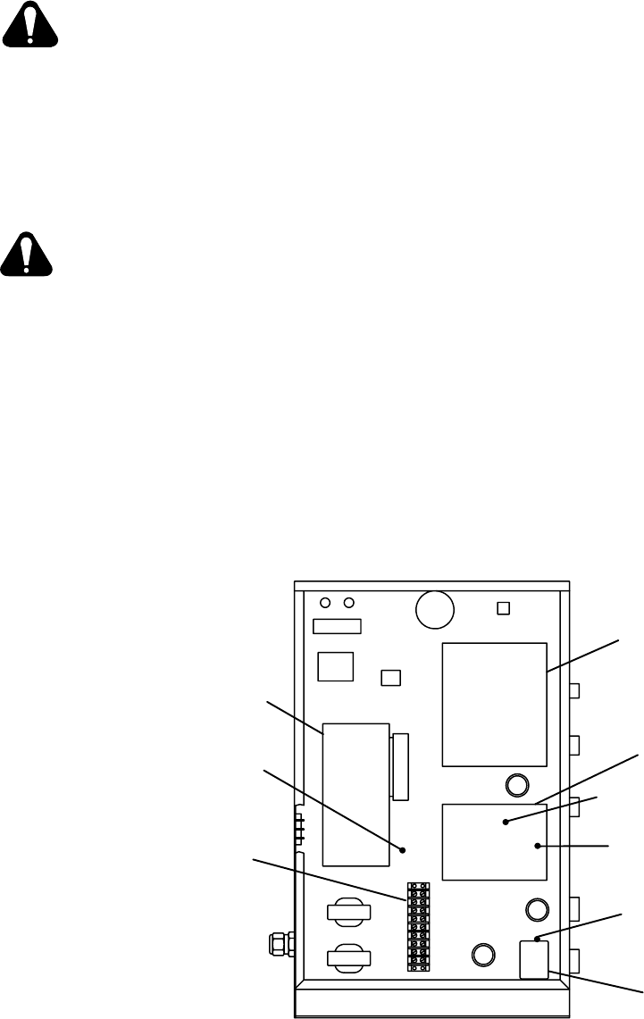
4. Make the following internal connections to the
Computer Interface (see Figure 3-2).
a. Remove jumper link between terminals B and C
on terminal strip 2T.
b. Connect lead 26 from the Interface panel to ter-
minal B on terminal strip 2T.
c. Connect lead 60 from the Interface panel to top
mounting screw on filter FL1.
d. Connect green lead from the Interface panel to
the ground stud located directly above terminal
strip 2T.
IMPORTANT:
Remove the outside star washer from the
ground stud to make room for the green lead terminal.
e. Remove plug PLG3 from receptacle RC1 on In-
terface Board PC4.
f. Connect plug PLG10 from the PAW Interface
panel to Interface Board PC4 receptacle RC1
where plug PLG3 was removed in Step 4e (plug
PLG3 is not connected for this application).
Ground Stud
Location
Motor Control
Board PC2
Terminal
Strip 2T
Filter FL1
Mounting Screw
Location
Interface
Board PC4
Voltage Control
Board PC1
PC4 Receptacle RC1
Location
Left Side View Of
Computer Interface
Ref. ST-139 887-C
PC4 Switch S1 Location
Figure 3-2. Computer Interface Internal Connections